Elenco Fiber Optics Voice Data Kit User Manual
Page 23
- 18 -
1111 8888
M
M
M
M oooo rrrr eeee FFFF iiii bbbb eeee rrrr aaa
a nnnn dddd LLLL eeee nnnn ssss eeee ssss
Lenses can focus images onto — and from — fiber bundles
.................................................................................................................................
In previous experiments we used a lens to focus images on the surface of a fiber optic faceplate
and Ulexite. In this activity you will demonstrate how a lens can also be used in reverse, focusing an
image of fiber(s) and projecting the light from fiber ends.
M
M
M
M aaa
a tttt eeee rrrr iiii aaa
a llll ssss N
N
N
N eeee eeee dddd eeee dddd ::::
Penlight with batteries
Black rubber penlight boot
2.2 mm (.088 inch) outside diameter jacketed optical fiber, .75 m (30 inches) long
Lens, double convex, approximately 25.4 mm (1 inch) diameter
Multifiber light guide constructed in Experiment 17
Masking tape*
* Not contained in this kit.
FFFF
OO
O
O LLLL LLLL OOO
O W
W
W
W
TTTT
HHHH EEEE SSSS EEEE
SSSS
TTTT EEEE PPPP SSSS
::::
•
Insert one end of the 2.2 mm (.088 inch) outside
diameter jacketed optical fiber into the hole in the
rubber boot and turn the penlight on.
•
Turn off room lights and close all the window
coverings. Leave one door open so you can see your
way around.
•
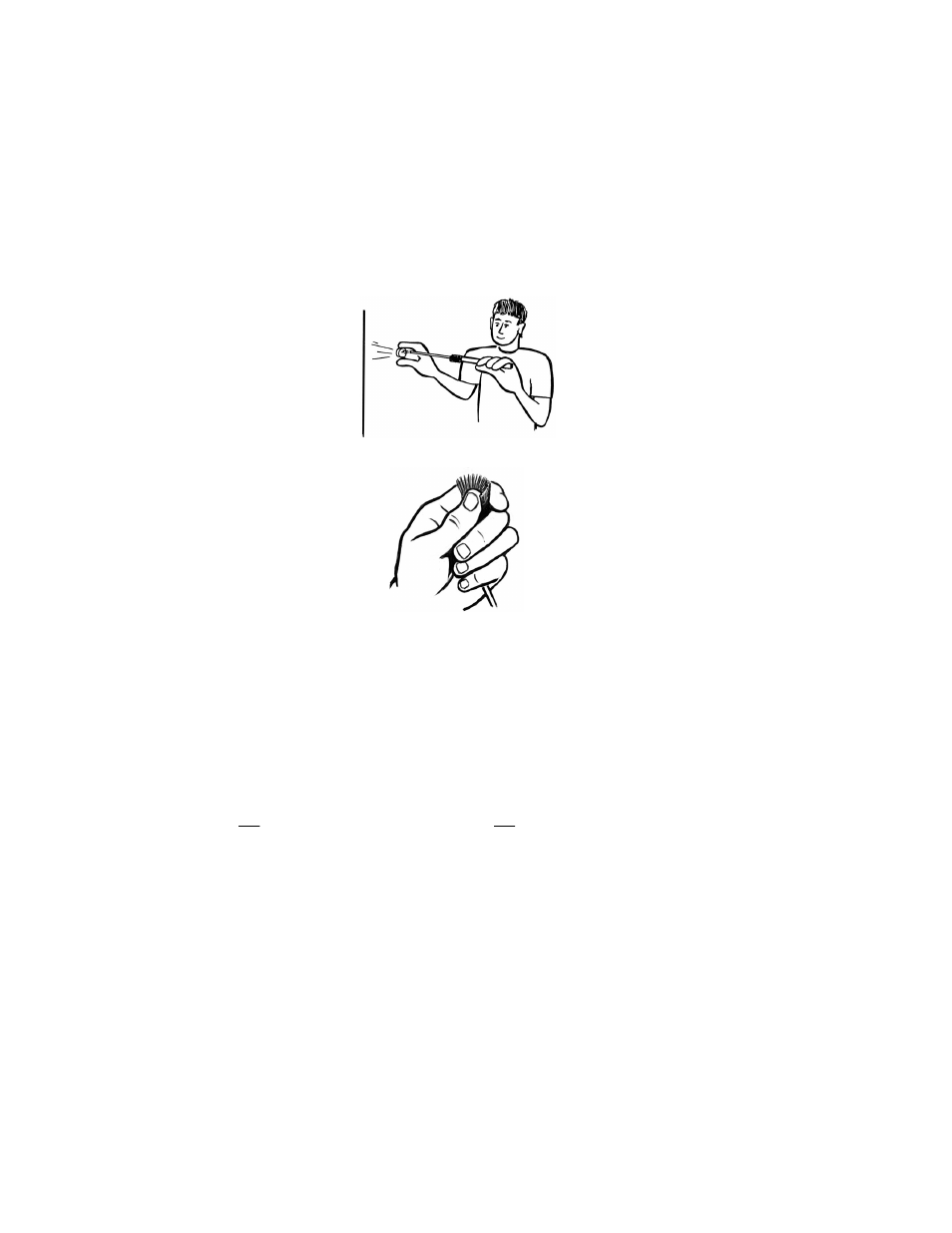
Stand about 1 meter (40 inches) away from a wall.
Hold the fiber and penlight in one hand and the lens
in the other, about 4 to 5 cm (1.6 to 2 inches) away
from the fiber end, as shown in the illustration.
Move the lens closer to the fiber end, then further
away, and observe the effect that the separation
distance has on the focused light which appears on
the wall.
•
Replace the jacketed optical fiber in the penlight
boot with the multifiber light guide that you
constructed in Experiment 17. Insert the end closest
to the heat shrink into the rubber boot.
•
Arrange the individual fibers in a crescent shape as
shown in the illustration, with all fiber ends flush
with each other. Hold the fibers in position with
masking tape.
•
Starting with the lens 4 to 5 cm (1.6 to 2 inches) away from the illuminated fiber tips, project
light through the lens and onto the wall. Observe the shape of the image produced on the wall.
R
R
R
R
EEEE SSSS UU
U
U LLLL TTTT SSSS
::::
When the distance between the fiber ends and the lens is slightly longer than the focal point of
the lens, light leaving the fiber ends will form an image on the wall. The shape of the image that the
lens produces will correspond to the shape of the fiber ends. The jacketed optical fiber and multifiber
bundle will produce round and crescent shapes, respectively. (In the crescent shape, you may be able
to see light from individual fibers.)
W
W
W
W
HHHH Y
Y
Y
Y
::::
The lens collects the light exiting each fiber and focuses or images it to some point in space
because of its focusing capability. The distance between the lens and the fibers where the image is
focused best will be just slightly longer than the focal length of the lens. The image formed on the wall
doesn't depend on the shape of the light leaving the fibers. It depends on the shape of the fiber where
the light exits.
1168