103k, Introduction, General overview – Elenco Fiber Optics Voice and Data Kit User Manual
Page 2: Identifying resistor values, Identifying capacitor values, Transmitter receiver fiber optic cable, Bands, 100v
INTRODUCTION
The FO-30 kit, an optical voice link, will introduce you to the wonderful world of fiber optics. By building this kit,
you will learn how fiber optics works and how it could be applied to the field of communication.
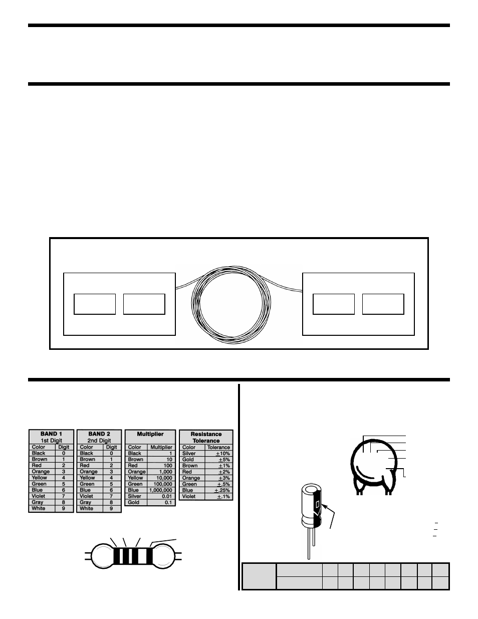
GENERAL OVERVIEW
-1-
Fiber optics is a medium linking two electronic
circuits. As shown in the block diagram below, this
FO-30 kit consists of three basic elements; they are
transmitter, fiber optic cable and receiver.
The Transmitter converts an electrical signal into a
light signal. The source, either a light-emitting-diode
(LED) or laser diode, does the actual conversion.
The drive circuit changes the electrical signal fed to
the transmitter into a form required by the source.
1
Fiber-optic cable is the medium for carrying the
light. The cable includes the fiber and its protective
covering.
2
The Receiver accepts the light and converts it back
into an electrical signal. The two basic parts of the
receiver are the detector, which converts it back into
an electrical signal, and the output circuit, which
amplifies and, if necessary, reshapes the electrical
signal.
3
The other parts which are not included in the
diagram consists of connectors which are used to
connect the fibers to the source and detector.
TRANSMITTER
RECEIVER
FIBER OPTIC CABLE
DRIVER
SOURCE
DETECTOR
OUTPUT
CIRCUIT
IDENTIFYING RESISTOR VALUES
Use the following information as a guide in properly identifying the
value of resistors.
IDENTIFYING CAPACITOR VALUES
Capacitors will be identified by their capacitance value in pF
(picofarads), nF (nanofarads), or
μF (microfarads). Most capacitors
will have their actual value printed on them. Some capacitors may
have their value printed in the following manner.
For the No.
0
1
2
3
4
5
8
9
Multiply By
1
10 100 1k 10k 100k .01 0.1
Multiplier
1
2
Multiplier
Tolerance
BANDS
Second Digit
First Digit
Multiplier
Tolerance
103K
100V
Maximum
Working Voltage
The value is 10 x 1,000 = 10,000pF or
.01
μF, ±10%, 100V
The letter M indicates a tolerance of +20%
The letter K indicates a tolerance of +10%
The letter J indicates a tolerance of +5%
Note:
The letter “R” may be used at times
to signify a decimal point; as in 3R3 = 3.3
1, 2, 3
The above paragraphs are reproduced by permission TECHNICIAN’S GUIDE TO FIBER OPTICS 2E (PAGE 2)
By Donald J Sterling, Jr. - DELMAR PUBLISHERS, INC., Albany, New York, Copyright 1993
Electrolytic capacitors have a
positive and a negative electrode.
The negative lead is indicated on
the packaging by a stripe with
minus signs and possibly
arrowheads.
Warning:
If the capacitor is
connected with
incorrect polarity, it
may heat up and
either leak, or
cause the capacitor
to explode.
Polarity
Marking
(+)
(–)