Assembly instructions for receiver, Figure d, Figure c – Elenco Fiber Optics Voice and Data Kit User Manual
Page 19: Figure a, Figure b, Figure f, Figure e
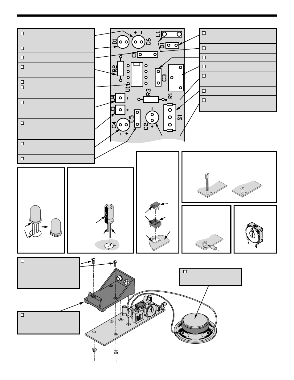
Q1 - Phototransistor
(see Figure D)
L1 - Lug (see Figure E)
C3 - .047
μF Mylar Cap. (473)
R1 - 200
Ω Pot (see Figure F)
R3 - 10
Ω 5% 1/4W Resistor
(brown-black-black-gold)
S1 - Switch
C2 - 47
μF Electrolytic Capacitor
(see Figure B)
C6 - 10
μF Electrolytic Capacitor
(see Figure B)
D1 - LED (see Figure A)
C1 - .047
μF Mylar Cap. (473)
R2 - 2.2k
Ω 5% 1/4W Resistor
(red-red-red-gold)
8-Pin IC Socket
U1 - LM386N Integrated Circuit
(see Figure C)
6” Black Wire - Strip 1/8” of
insulation off of both ends of the
wire.
6” Red Wire - Strip 1/8” of
insulation off of both ends of the
wire.
C4 - 220
μF Electrolytic Capacitor
(see Figure B)
C5 - .047
μF Mylar Cap. (473)
Figure D
Insert the phototransistor into the PC board in the
direction shown.
Figure C
Insert the IC socket into
the PC board with the
notch in the direction
shown on the top
legend. Solder the IC
socket into place. Insert
the IC into the socket
with the notch in the
same direction as the
notch on the socket.
Figure A
Mount the LED with the
flat side in the same
direction as marked on
the top legend.
Figure B
Electrolytics have a polarity marking
indicating the (–) lead. The PC board is
marked to show the lead position.
Warning: If the capacitor is connected
with incorrect polarity, it may heat up and
either leak or cause the capacitor to
explode.
Figure F
ASSEMBLY INSTRUCTIONS FOR RECEIVER
-18-
Mount flush
with PC board
(–) (+)
Polarity
Mark
PC Board
Notch
Marking
Flat
Notch
IC
Socket
IC
Speaker and 2 Wires
Solder the wires to the correct
position as shown.
– +
9V Battery Holder
Solder the 9V battery holder to
pad J1 and J2 in the correct
position as shown.
Screws and Nuts
Mount the two screws in the
position as shown. Place the nuts
on the screws and tighten them
from the back side of the PC
board.
Figure E
Mount the lug as shown.
Make sure that the
phototransistor lens lines
up with the lug hole.