Elenco Robotics User Manual
Page 6
5
Step 2
Take the motor (10) and insert it into the large hole (motor housing) from the top side of
the chassis, so that the "worm wheel" of the motor connects (meshes) with the cog wheel
that drives the back wheels.
Place the gearbox cover (8) on the gearbox
and secure it with 4 screws.
After you have secured the gear box cover, secure the motor.
Between the motor and the switch there is a post,
take the screw with the shape as shown in the picture, tighten it to the post, this will hold the
motor in place.
Step 3
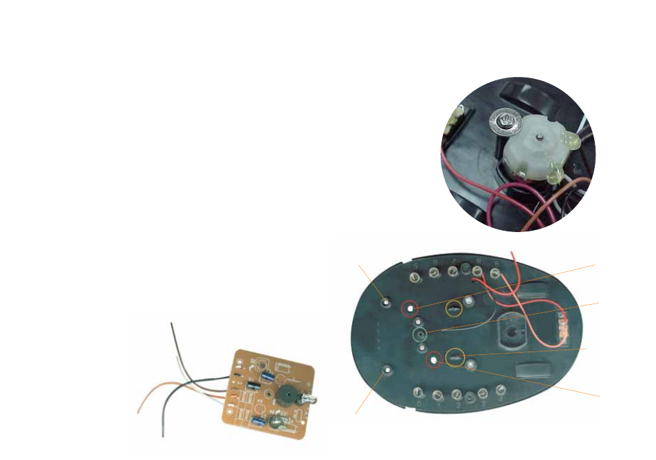
Take the Module (printed circuit) and very carefully place it at the front
of the chassis, inserting the plastic rod into one of the two holes,
either on the right or the left, depending on the module.
The plastic rod is the trimmer, used for adjusting the sensivity.
In the middle of the module there is a small hole for the small screw
in your kit and two small holes at the back of the module that fit onto
two small pins on the chassis. Using your screwdriver tighten the screw
in place on the pillar on the chassis. Using a small screwdriver tighten
the screw in place on the pillar
of the chassis. When secured,
take the wires and place each
wire next to one of the springs.
Electronic Module
Pin
Pin
Trimmer
Trimmer
Pillar
Module
Support