Advanced troubleshooting, Customer service – Elenco Circuit Maker Skill Builder 125 User Manual
Page 9
Advanced Troubleshooting
(Adult supervision recommended)
-8-
ELENCO
®
is not responsible for parts
damaged due to incorrect wiring.
If you suspect you have damaged parts,
you can follow this procedure to
systematically determine which ones need
replacing:
1.
2.5V lamp (L1), motor (M1), speaker
(SP), and battery holder (B1):
Place
batteries in holder. Place the 2.5V lamp
directly across the battery holder, it
should light. Do the same with the
motor (motor + to battery +), it should
spin to the right at high speed. “Tap” the
speaker across the battery holder
contacts, you should hear static as it
touches. If none work then replace your
batteries and repeat, if still bad then the
battery holder is damaged. If the motor
spins but does not balance the fan,
check the black plastic piece on the
motor shaft; it should have 3 prongs.
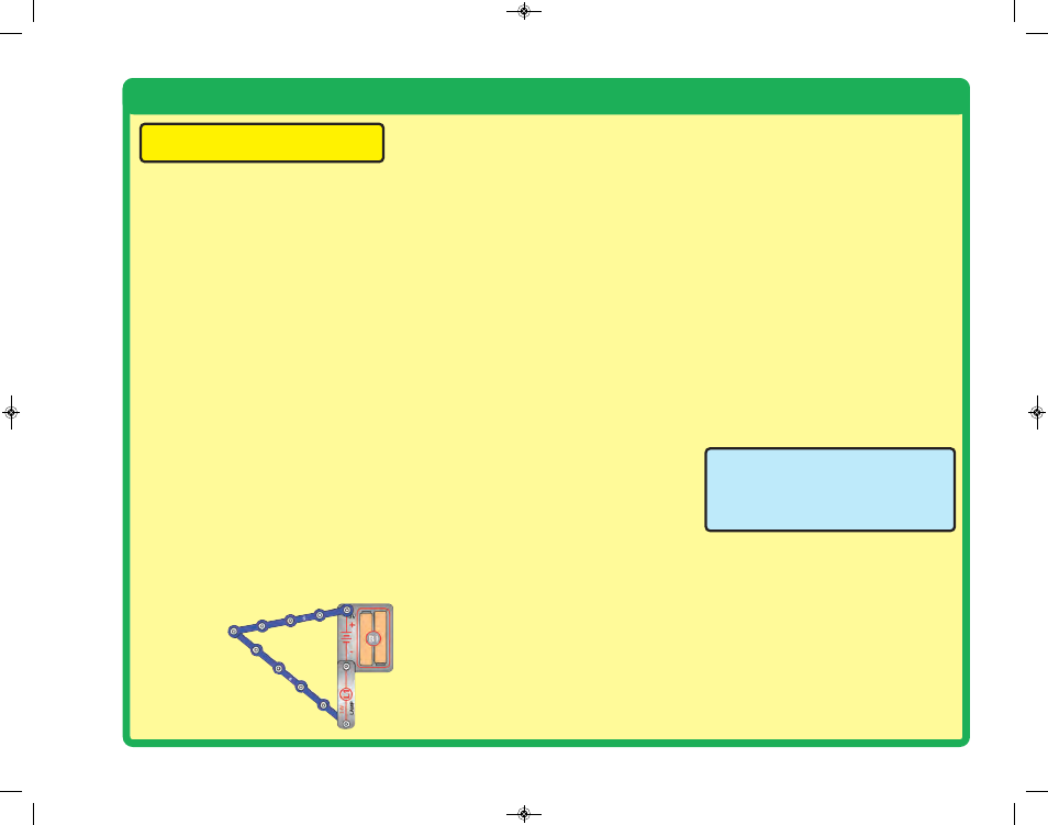
2.
Snap wires:
Use this mini-circuit to test
the 5-snap and 6-snap wires. The lamp
should light. Then test each of the 1-
snap, 2-snap, 3-snap, and 4-snap
wires by connecting them
b e t w e e n
the ends of
the 5-snap
and 6-snap.
3.
Slide switch (S1) and Press switch
(S2):
Build Project #1, if the lamp (L1)
doesn’t light then the slide switch is
bad. Replace the slide switch with the
press switch to test it.
4.
100W resistor (R1), 1KW resistor
(R2), and LED (D1):
Build Project #11
except initially use the speaker (SP) in
place of the resistor, the LED should
light. Then, replace the speaker with
the 100W resistor; the LED should still
light. Then, replace the 100W resistor
with the 1KW resistor; the LED should
light but not as brightly.
5.
Alarm IC (U2):
Build Project #21, you
should hear a siren. Then place a 3-
snap wire between grid locations A1
and C1, the sound is different. Then
move the 3-snap from A1-C1 to A3-C3
to hear a third sound.
6.
Music IC (U1):
Build Project #86 but
use the press switch (S2) in place of
the photoresistor (RP). Turn it on and
the LED (D1) flickers for a while and
stops, it resumes if you press and hold
down the press switch. Then touch a 3-
snap wire across base grid points A1
and C1 and the flickering resumes for a
while.
7.
Space war IC (U3) and photoresistor
(RP):
Build Project #4, both switches
(S1 and S2) should change the sound.
Then replace the slide switch (S1) with
the photoresistor, waving your hand
over it should change the sound.
8.
NPN transistor (Q2):
Build Project
#31. When both switches are on, the
lamp lights and motor spins. If one
switch is off, nothing happens.
9.
470mF capacitor (C5):
Build Project
#50, then press and release the switch.
The LED should go off slowly.
Customer Service
Call toll-free: (800) 533-2441
e-mail: [email protected]
CM-125_Manual_031514.qxp_CM-125_Manual_031514 4/2/14 12:19 PM Page 9