Project #644, Nor gate project #645, Xor gate – Elenco Projects 512-692 User Manual
Page 64
-63-
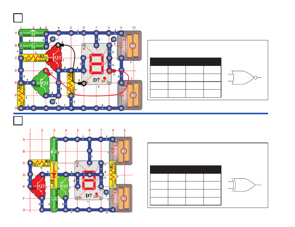
Project #644
OBJECTIVE: To demonstrate the operations of the NOR gate.
NOR Gate
Project #645
OBJECTIVE: To demonstrate the operations of the “exclusive
or” XOR gate.
XOR Gate
The NOR gate works the opposite of the OR. In the circuit, the S1 &
S2 switches represent inputs A & B, and the D7 display represents
output Q.
In an XOR gate the output “Q” is only high when inputs “A” or “B” is set
high (1).
Using the chart, set the switches (S1 & S2) to the different states. The
display (D7) lights the letter “H” only when either switch is turned on.
A
B
Q
D7
0
0
1
“H”
1
0
0
“L”
0
1
0
“L”
1
1
0
“L”
A
B
Q
D7
0
0
0
–
1
0
1
“H”
0
1
1
“H”
1
1
0
–
A
B
Q
XOR Gate
A
B
Q
NOR Gate
To learn more about how circuits work, visit www.snapcircuits.net or page 85 to find out about our Student Guides.
This manual is related to the following products: