Project #642, Nand gate project #643, Or gate – Elenco Projects 512-692 User Manual
Page 63
-62-
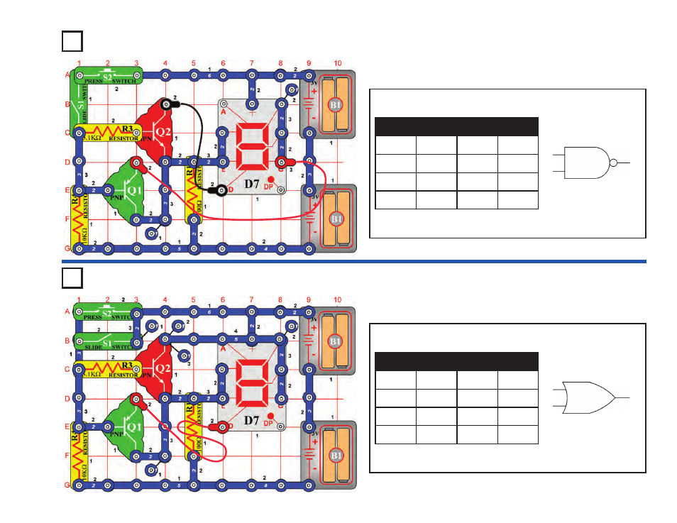
Project #642
OBJECTIVE: To demonstrate the operations of the NAND gate.
NAND Gate
Project #643
OBJECTIVE: To demonstrate the operations of the OR gate.
OR Gate
The NAND gate works the opposite of the AND as shown in the logic
chart.
In the circuit, the S1 & S2 switches represent inputs A & B, and the D7
display represents output Q.
The basic idea of an OR gate is: If A OR B is 1 (or both are 1), then
Q is 1.
In the circuit, the S1 & S2 switches represent inputs A & B, and the D7
display represents output Q.
A
B
Q
D7
0
0
1
“H”
1
0
1
“H”
0
1
1
“H”
1
1
0
“L”
A
B
Q
D7
0
0
0
“L”
1
0
1
“H”
0
1
1
“H”
1
1
1
“H”
A
B
Q
NAND Gate
A
B
Q
OR Gate
This manual is related to the following products: