Advanced troubleshooting, Elenco, Electronics, inc – Elenco R/C Snap Rover® User Manual
Page 9
-8-
Advanced Troubleshooting
(Adult supervision recommended)
Elenco
®
Electronics is not responsible for parts damaged due to
incorrect wiring.
If you suspect you have damaged parts, you can follow
this procedure to systematically determine which ones
need replacing:
1.
Rover body and jumper wires:
Flip the Rover body
upside down and make sure the wheel mechanisms
are clean. Install batteries in the Rover body and
connect jumper wires to the Rover rear as shown; two
wheels should move. Replace the orange and gray
jumper wires with each of the other colors to see if any
of the jumpers are damaged. If the wheels don’t move
for any combination of wires, then the Rover body is
damaged. Remove the gray wire; four LEDs on the side
should light.
Now move the jumper wires to test the other two
wheels, if they don’t move then the Rover body is
damaged. Remove the gray wire, four LEDs on the side
should light.
2.
Slide switch (S1):
Build project 6 (Helpless Rover) and test the switch by
making it turn the wheels on/off.
3.
Snap wires:
Build project 6 but replace the switch with each of the snap wires
(including the 1-snaps), test them one at a time.
4.
Horn (W1), LED (D4), 100
Ω and 1KΩ resistors (R1, R2):
Build this mini-
circuit and turn on the switch, the horn should make a loud noise or it is
damaged. Replace the 3-snap with the 100
Ω resistor, the sound should be a
little less loud or the resistor is defective. Replace the horn with the LED (“+”
side on left, and keep the resistor in), the LED should be bright or it is
damaged. Now replace the 100
Ω resistor with each of the 1KΩ resistors (one
at time), the LED•should still be bright or the resistor is damaged.
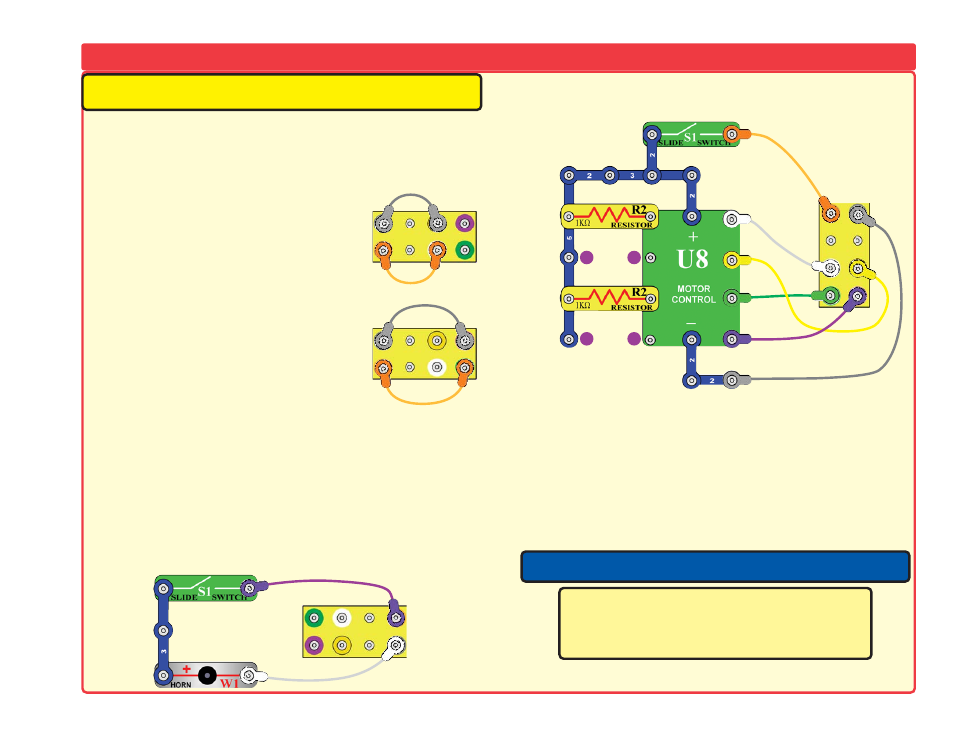
5.
Motor Contol (U8) module:
Build this circuit and turn it on, both sets of
wheels should turn forward. Now shift the 1K
Ω resistors (R2) to be across
points A-B and C-D; the wheels should turn backwards.
6.
0.02
μF and 100μF•capacitors (C1, C4N):
Build project #14. Charge each of
the 100
μF capacitors as directed and test that it lights the LED, if it doesn’t then
it is damaged. Now do this using the 0.02
μF capacitor but look closely at the
front of the LED, you should see a brief dim flash if the capacitor is working.
7.
Remote control unit and R/C Receiver (RX1):
Build project #2 and test that
the wheels, horn (W1), and LED (D4) can be controlled by the remote control
unit as described. Be sure you have built the circuit correctly and have good
batteries in both the Rover and remote control. Have the A-B-C switches on the
remote control and R/C receiver set to the same channel, have turned on the
remote control turned on and its antenna extended, and make sure it is not not
being interfered with by other remote control transmitters.
A
ROVER•REAR
B
C
D
RO
VER•R
EAR
RO
VER•R
EAR
Elenco
®
Electronics, Inc.
150 Carpenter Avenue • Wheeling, IL 60090 U.S.A.
Phone: (847) 541-3800 • Fax: (847) 520-0085
e-mail: [email protected] • Website: www.elenco.com
Note: If you have a more advanced model, there are additional tests in your other
project manual(s).
You may order additional / replacement parts at:
www.snapcircuits.net
R
O
VER•
R
EAR