Display Devices SE-B6-10 Soffit Series User Manual
Page 3
01-07
3
tel: 303.412.0399
www.displaydevices.com
fax: 303.412.9346
5880 Sheridan Blvd., Arvada, Colorado 80003
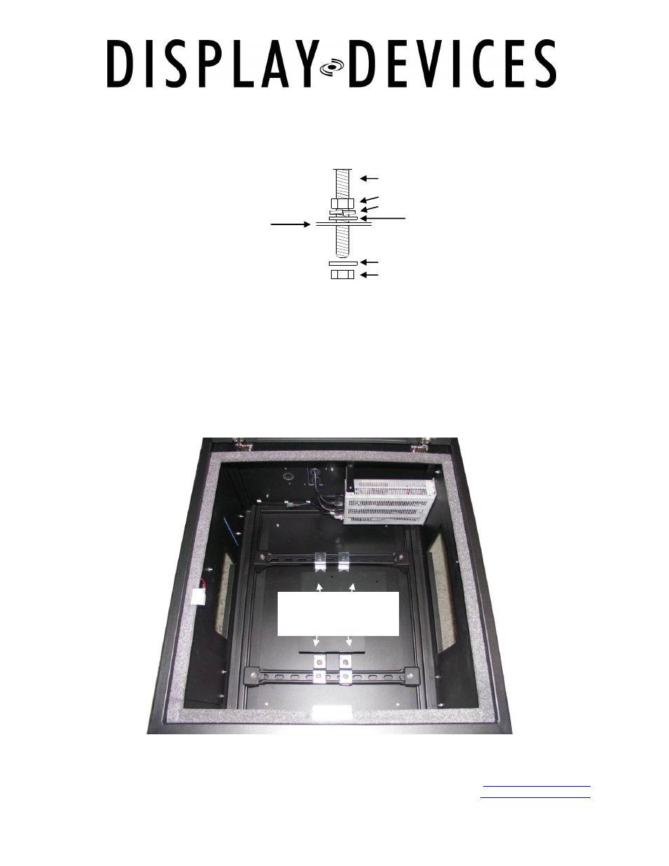
4.)
Raise the unit up on a material lift to the appropriate vertical height. Be sure to have a
sufficient amount of threaded rod to provide leveling room. Add hardware as follows for
leveling: above unit – nut/lock washer/flat washer; underside of unit – washer and nut - do
not tighten yet.
5.)
Use a bubble level to level the unit front-to-back and side-to-side. Tighten hardware.
6.)
To attach the fire dampers to the intake and exhaust ports use the enclosed Phillips-head
sheet metal screws.
7.)
Add runs of ductwork on the intake and exhaust fire dampers. Addition of ducts disperses
the sound further away from the projector. Sound-isolating ductwork is recommended. If
additional sound dampening is desired, we recommend an auto sound insulation material.
8.)
Mounting points for a projector mount or lift are pre-installed inside the top of the cavity. The
structural channel can be loosened and adjusted for the proper width of the mount or lift.
Threaded rod
Nut
Flat washer
Split lock washer
Flat washer
Nut
Sound Enclosure
Mounting rails with
pre-installed rods
(under plate)