Lift preparation – Display Devices Lifts up up 400 lbs User Manual
Page 5
1/17/07
5
Lift Preparation
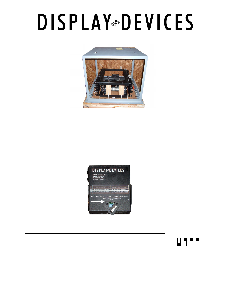
Unpack Lift – remove phillips head screws & lag screws securing frame & lift to the
pallet. (photo of LCD-100 with Option 4). The lift is shipped upside down. Leave the
wood blocks and plastic tie wraps in place.
Control Box
NOTE:
The factory default setting will not change for most installations.
SET DIP SWITCHES before you install the lift. Be sure there is no power connected to
the lift. The control box is located inside the lift on the upper frame. Depending upon
your lift model the location and orientation of the control box varies.
Dip switches are located under the small access panel on the Control Box attached to
the lift frame. Use a 1/16” Hex driver to open.
ON
OFF
SW1
Aux AC Trigger (see SW2 below)
Aux AC Trigger is on all the time
SW2
Aux AC Trigger upon going down
Aux AC Trigger at show position
SW3
12V out turns off upon going up
12V out turns off at top position
SW4
12V out turns on upon going down 12V out turns on at show position
Dip Switch SW1: configuration only works in automatic mode.
Set the 12 volt trigger and AC Trigger based on your system design.
1 2 3 4
ON
OFF
Default setting