Wall mounting for panoramics with 24” marker tray – Da-Lite IDEA Panoramic User Manual
Page 5
5
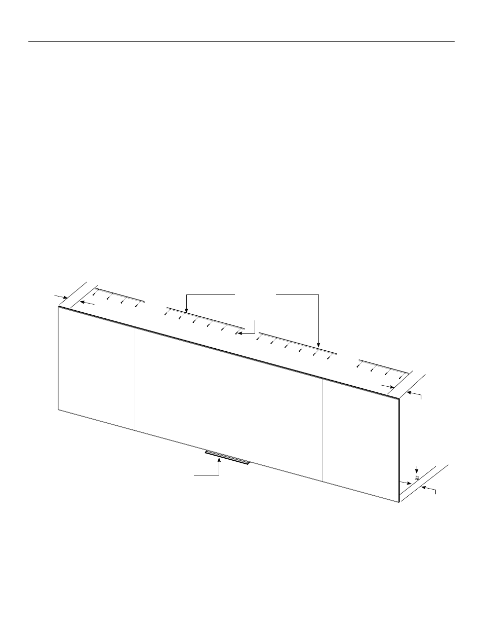
Wall Mounting for Panoramics with 24” Marker Tray
NOTE: The screen is shipped with four wall brackets and lengths
shipped vary by screen size. Two brackets will be used on the
center panel and one bracket on each of the side panels.
Measure gap on each side panel to determine which two
brackets will be used with these panels. These brackets will be of
an equal length. The remaining two brackets (also of an equal
length) will be used to hold the weight of the center panel. Use
appropriate mounting hardware for the wall type and to
accommodate for the screen’s total hanging weight.
1. Secure the two center panel wall brackets to wall studs at the
desired height. The outside edge of each wall bracket must be
no greater than 5” away from the left or right panel seams. You
will need at least 1” clearance above the drilled holes to hang the
screen.
2. Secure the two side panel wall brackets to wall studs at the height
selected in Step 1. Each side panel wall bracket should be
centered between the seam brace and left or right outside edge
of the frame when mounted to the wall (Figure 3).
NOTE: Do not proceed if all four brackets are not level with each
other or a gap may appear between each of the panels when
mounted.
3. To install the (2) center panel L-brackets, you must measure the
overall height of the screen frame and subtract 1 1/8”. Using that
dimension, measure down from the top edge of each of the
center wall brackets and mark the wall for two screw holes. The
outside edge of each center panel L-bracket must be no greater
than 5” away from the left or right panel seams (Figure 3).
4. Secure the two center panel L-brackets to the wall at the marked
locations. The longest side of the two center panel L-brackets
should be pointing upwards when secured in order to hide the
L-brackets behind the screen frame once the screen is installed
(Figure 3).
Wall Brackets
L-Bracket
No More
than 5”
No More
than 5”
No More
than 5”
Screws (Not Supplied)
Tray Installed in Step 8
Figure 3