Dio (ico300-dio), Watchdog timer (wdt), Restore bios optimal defaults (jp2) – Axiomtek ICO300 User Manual
Page 12: System led
ICO300 Series U
ser’s Manual
Introduction
4
1.2.11
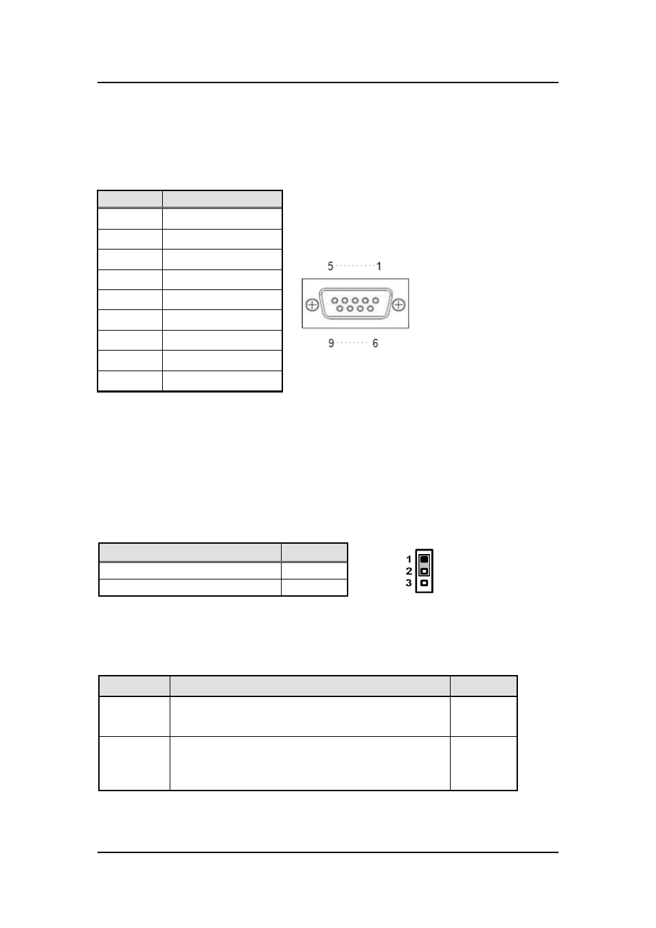
DIO (ICO300-DIO)
One DB9 female connector supports 8 bits TTL level programmable digital
input/output
Pin
Signal
1
DIO0
2
DIO1
3
DIO2
4
DIO3
5
DIO4
6
DIO5
7
DIO6
8
DIO7
9
GND
1.2.12
WatchDog Timer (WDT)
1~255 seconds or minutes; up to 255 levels
.
1.2.13
Restore BIOS Optimal Defaults (JP2)
Put jumper clip to pin 2-3 for a few seconds then move it back to pin 1 -2. Doing
this procedure can restore BIOS optimal defaults .
1.2.14
System LED
There are showed the LED
’s indicators and functional descriptions.
LED Name
Description
Color
ACT
Indicate the storge status and it
’s flashing when storge
access.
Green
PWR
Indicate the Power status. When the DC input is acceptable,
the LED will ON.
Yellow
Function
Setting
Normal (Default)
1-2 close
Restore BIOS optimal defaults
2-3 close