Com connectors (com34 and com56), Gpio connector (jdio), 4 gpio connector (jdio) – Axiomtek MANO861 User Manual
Page 19
MANO861 Mini ITX Board
Board and Pin Assignments
11
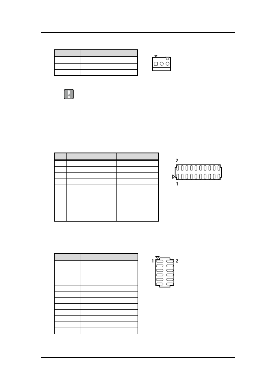
System fan interface is available through SYS_FAN1, see table below.
1
Caution
Do not forget to connect the fan cables to the fan connectors. Insufficient
air flow inside the system may damage the motherboard components.
These are not jumpers! DO NOT place jumper caps on the fan connectors.
2.4.3
COM Connectors (COM34 and COM56)
These connectors are for serial (COM) ports. Connect the serial port module cable to
this connector, then install the module to a slot opening at the back of the system
chassis.
COM34, COM56
2.4.4
GPIO Connector (JDIO)
This connector is for GPIO function.
Pin
Signal
1
GND
2
SYSFAN1_VCC(PWM)
3
SYSFAN1_IO
Pin Signal
Pin Signal
1
DCD#
2
DSR#
3
RXD
4
RTS#
5
TXD
6
CTS#
7
DTR#
8
RI#
9
GND
10
GND
11
DCD#
12
DSR#
13
RXD
14
RTS#
15
TXD
16
CTS#
17
DTR#
18
RI#
19
GND
20
GND
Pin
Signal
1
SIO_GPIO0
2
SIO_GPIO4
3
SIO_GPIO1
4
SIO_GPIO5
5
SIO_GPIO2
6
SIO_GPIO6
7
SIO_GPIO3
8
SIO_GPIO7
9
SMB_CLK_MAIN
10
SMB_DAT_MAIN
11
GND
12
VCC GPIO