Rear panel connectors, Fan connectors (cpu_fan and sys_fan1), 1 rear panel connectors – Axiomtek MANO861 User Manual
Page 18: 2 fan connectors (cpu_fan and sys_fan1)
MANO861 Mini ITX Board
10
Board and Pin Assignments
2.4.1
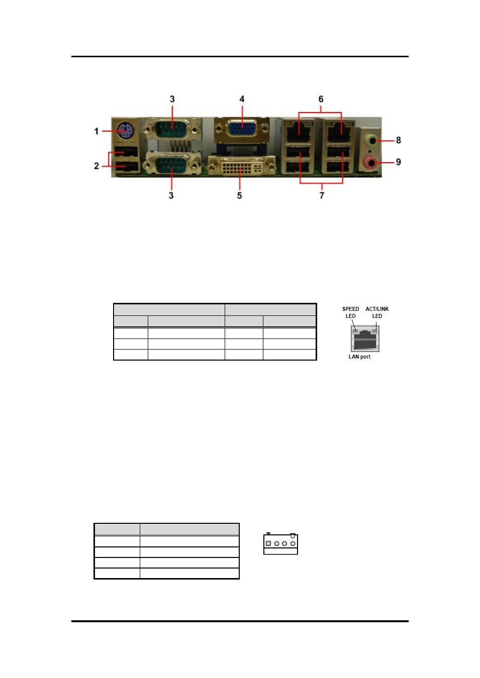
Rear Panel Connectors
1.
PS/2 port (purple). This port is for a PS/2 keyboard and mouse.
2.
USB 2.0 ports 5 and 6. These two 4-pin Universal Serial Bus (USB) ports are
available for connecting USB 2.0 devices.
3.
Serial connectors. These 9-pin COM1 and COM2 ports are for serial devices.
4.
VGA port. This 15-pin VGA port connects to a VGA monitor.
5.
DVI-D port. This 29-pin DVI-D port is for a DVI monitor.
6.
LAN (RJ-45) ports. Each of these ports allows Gigabit connection to a Local Area
Network (LAN) through a network hub. Refer to the table below for the LAN port
LED indications.
7.
USB 2.0 ports 1~4. These four 4-pin Universal Serial Bus (USB) ports are
available for connecting USB 2.0 devices.
8.
Line-out port (Green). This port connects a headphone or a speaker. In 4-channel,
6-channel, and 8-channel configuration, the function of this port becomes front
speaker-out.
9.
Microphone port (pink). This port connects a microphone.
2.4.2
FAN Connectors (CPU_FAN and SYS_FAN1)
The fan connectors support cooling fans of 280mA (3.36 W max.) at 4800rpm or a total
of 1A~2.22A (26.64W max.) at +12V. Connect the fan cables to the fan connectors on
the motherboard, making sure that the black wire of each cable matches the ground pin
of the connector.
CPU fan interface is available through CPU_FAN, see table below.
SPEED LED
ACT / LINK LED
Status Description
Status
Description
OFF
10Mbps connection
OFF
No link
Orange
100Mbps connection
Green
Link
Green
1Gbps connection
Blinking
Data activity
Pin
Signal
1
GND
2
+12V
3
Tach
4
PWM
1