Lvds connector (jlvds1), Signal description – lvds connecter (jlvds), 1 signal description – lvds connecter (jlvds) – Avalue EBM-A50M User Manual
Page 21
Quick Installation Guide
EBM-A50M Quick Installation Guide
21
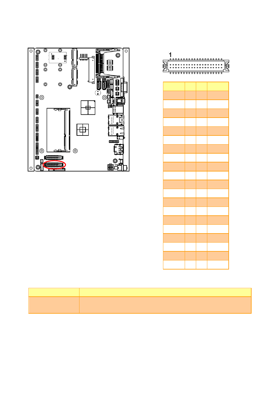
2.3.21
LVDS connector (JLVDS1)
Signal PIN PIN Signal
+5V
2
1
+3.3V
+5V
4
3
+3.3V
I
2
C_DAT
6
5
I
2
C_CLK
GND
8
7
GND
Txout0
10
9
Txout1
Txout0# 12
11 Txout1#
GND
14
13
GND
Txout2
16
15
NC
Txout2# 18
17
NC
GND
20
19
GND
NC
22
21
NC
NC
24
23
NC
GND
26
25
GND
NC
28
27
NC
NC
30
29
NC
GND
32
31
GND
Txclk
34
33
NC
Txclk#
36
35
NC
GND
38
37
GND
+12V
40
39
+12V
2.3.21.1 Signal Description
– LVDS Connecter (JLVDS)
Signal
Description
I
2
C_DAT, I
2
C_CLK
I
2
C interface for panel parameter EEPROM. This EERPOM is mounted on the
LVDS receiver. The data in the EEPROM allows the EXT module to automatically
set the proper timing parameters for a specific LCD panel.
See also other documents in the category Avalue Hardware:
- ECM-QM87R (74 pages)
- ECM-BYT2 (71 pages)
- ECM-DX2 (20 pages)
- ECM-BYT (73 pages)
- ECM-KA (24 pages)
- ECM-KA (72 pages)
- ECM-QM77 (24 pages)
- ECM-QM77 (89 pages)
- ECM-CDV (20 pages)
- ECM-CDV (70 pages)
- ECM-QM57 (79 pages)
- ECM-QM57 (24 pages)
- ECM-QB (20 pages)
- ECM-QB (67 pages)
- ECM-PNV (24 pages)
- ECM-PNV (105 pages)
- ECM-PNV (77 pages)
- ECM-VX900 (24 pages)
- ECM-VX900 (74 pages)
- ECM-A50M (24 pages)
- ECM-A50M (77 pages)
- ECM-CX700 (20 pages)
- ECM-LX800W (24 pages)
- ECM-LX800W (105 pages)
- ECM-LX800D (20 pages)
- ECM-LX800D (94 pages)
- ECM-LX800 (101 pages)
- ECM-LX800 (24 pages)
- EPI-QM87 (77 pages)
- EPI-QM77 (24 pages)
- EPI-QM77 (86 pages)
- EPI-QM57 (20 pages)
- EPI-QM57 (80 pages)
- EPI-LX800 (20 pages)
- EPI-LX800 (107 pages)
- EPI-LX800 (24 pages)
- EPI-QM67 (24 pages)
- EPI-QM67 (91 pages)
- EBM-BYT (75 pages)
- EBM-QM87U (75 pages)
- EBM-CDV (82 pages)
- EBM-PNV (24 pages)
- EBM-PNV (79 pages)
- EBM-A50M (79 pages)