AValon RF DX-02 Series User Manual
Page 8
AVALON RF, INC.
Page 5 of 20
DX402/DX502/DX602 User’s Guide & Operating Manual
2.2 Antenna Inputs, total of 2 (Circles 1 & 8 on front panel).
a) DX402: The tuning frequency range is 56MHz-802MHz, VSB
modulated. The antenna connectors are “F” type with a 75
Ω
(ohm) impedance.
b) DX502: The tuning frequency range is 900-928 MHz, FM
modulated. The antenna connectors are “F” type with a 75
Ω
(ohm) impedance. An option extends the range from 900 to 2150
MHz.
c) DX602: The tuning frequency range is 2400-2500 MHz, FM
modulated. The antenna connectors are SMA type with a 50
Ω
(ohm) impedance. An option extends the range from 2150 to 2500
MHz.
2.3 Video Output – Broadcasting (Option 61) (Circle 4 on rear panel)
Video output connector is a BNC type with a 75
Ω
(ohm) impedance.
a) Output is NTSC/PAL/RS170A/CCIR baseband from 20 Hz to 5.5
MHz in broadcast mode and 20 HZ to 4.0 MHz in reference mode.
a) Output amplitude is 1 Vp.p. with negative sync tips of 0.3 Vp.p.
2.4
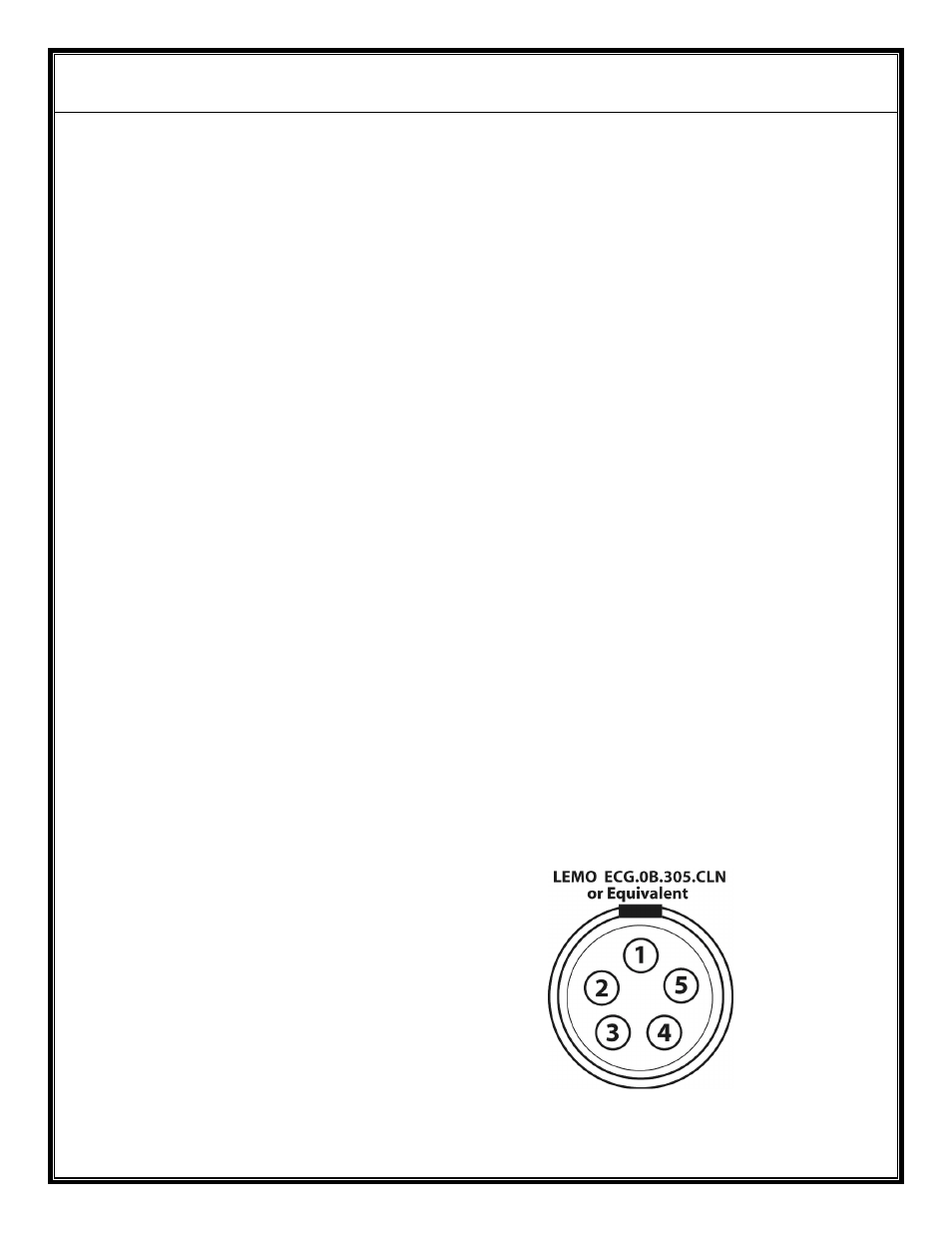
Audio Outputs – Broadcasting (Option 61) (Circle 2 on rear panel)
Audio output is through a 5 pin connector located on the rear panel.
Pin 1 – Audio Return
Pin 2 – Audio 1 Output
Pin 3 – No Connection
Pin 4 – RS232 Return
Pin 5 – RS232 Input
Figure E – Audio Output(s)