AValon RF DX-02 Series User Manual
Page 10
AVALON RF, INC.
Page 7 of 20
DX402/DX502/DX602 User’s Guide & Operating Manual
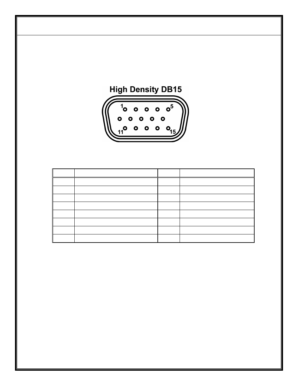
2.7 Interface
-
Security Version (Figure C, circle 6).
The interface is through a High Density DB15 connector (Figure G)
on the rear panel of the DX602.
Figure G – Interface - Security Version
Pin # Function
Pin # Function
1
Power Input
9
Signal Ground
2
Video Output
10
Telemetry 1 Output
3
Video Return Ground
11
Alarm Output
4
Audio 1 Output
12
RS-485 I/O ‘A’
5
Microphone Input
13
RS-485 I/O ‘B’
6
Microphone Bias
14
Telemetry 2 Output
7
RS232 Input
15
Telemetry 3 Output
8
Power Return Ground
2.7.1 Power Input (pins 1 and 8).
a) The DX602 operates off a 9Vdc to 16Vdc unregulated voltage
source with a ripple of less than 0.5Vp.p.
b) Input current at an input voltage of 12Vdc is under 0.6 Amps.
c) Power is switched via an ON/OFF mechanical switch.
d) The DX602 power input is protected against over voltage and
reverse polarity.
2.7.2 Video Output (pins 2 and 3).
a) The DX602 video output is NTSC/PAL/RS170A/CCIR
base-band, 75 Ohm.
b) Output amplitude is 1 V(p.p.) with negative sync tips of 0.3
V(p.p.)