B. test equipment – Advanced Control Technologies SCOPE-TEST2 (PCC OSCILLOSCOPE ADAPTOR TOOLDUAL LEAD) User Manual
Page 4
4
ADVANCED CONTROL TECHNOLOGIES, INC.
Indianapolis, Indiana 46278 (800) 886-2281
Scope-Test2
P/D 081399
B. TEST EQUIPMENT:
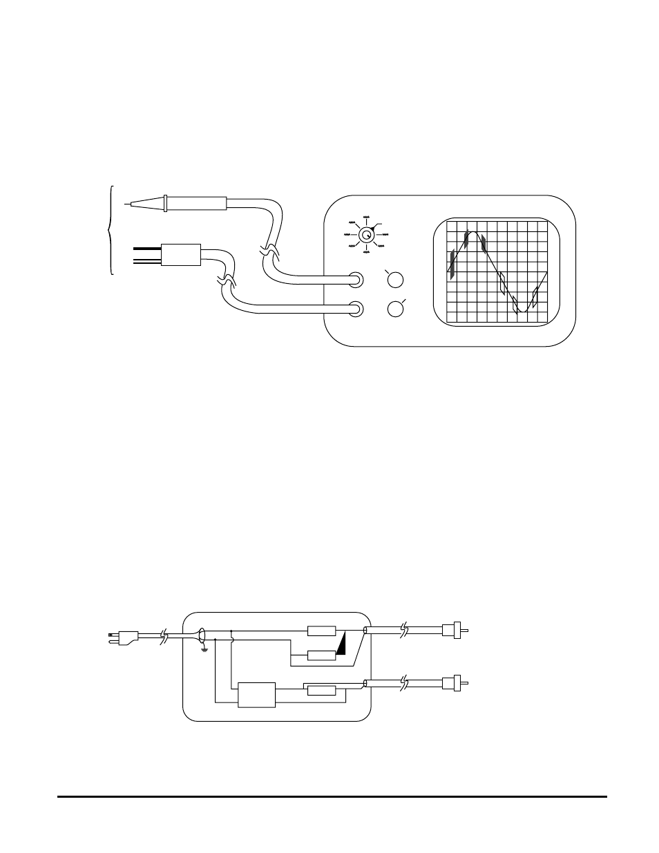
In order to display a very small PCC signal (sometimes well below 25mv) while also showing a 339vpp, 60Hz sine wave,
a dual trace oscilloscope is recommended. The first trace, input “A”, is set to display one cycle as described on the previous
page, while the second trace, input “B”, is set to display only the bursts of 120kHz. To filter out the high voltage, 60Hz
power and only allow the small voltage 120kHz signal to pass through to the oscilloscope on input “B”, a CP000 (Passive
Coupler, 1:1 ratio) is recommended.
The diagram above shows how the display would appear when viewed on a properly adjusted oscilloscope. The oscilloscope
sweep time is set to 1ms/division and fine adjusted to a time base that allows for only one sine wave. It also shows a 120v
sine wave which has been attenuated to 1/10th its original voltage by the scope probe and placed into channel “A”. The
vertical control for channel “A” is set to 5v/div.
Unlike the high voltage probe, the PCC signal is not reduced by the 1:1 probe and enters channel “B” which is set for .1v/
division. When the two traces are added together (“A+B”) it gives the technician an exaggerated view of the PCC signal
superimposed onto a greatly reduced 60Hz sine wave.
It would be awkward for any technician to attempt to do this type of field testing without having practiced in the safety and
unhurried comfort of one’s own test bench. For that reason, it is recommended that the technician explore testing and
troubleshooting under controlled conditions before having to do it in unfamiliar surroundings.
Many technicians find that building an oscilloscope “test box” (SCOPE TEST 2 also available from ACT) is not only an
excellent training aid but makes field troubleshooting easier. A basic diagram is shown below.
(Page 75, PCC Reference Manual)
X10 Probe
Sweep Time/div.
1 ms.
5v/div
}
}
.1v/div
A
B
CP000
To
Line
60 Hz
≈ 40 vpp
To
Scope
To
Scope
PCC Signal
Line
Neutral
Black
White
Black
White
1 meg
Ω
100 K
Ω
100
Ω
CP000