Xii. basic troubleshooting: b. test equipment – Advanced Control Technologies SCOPE-TEST2 (PCC OSCILLOSCOPE ADAPTOR TOOLDUAL LEAD) User Manual
Page 2
2
ADVANCED CONTROL TECHNOLOGIES, INC.
Indianapolis, Indiana 46278 (800) 886-2281
Scope-Test2
P/D 081399
XII. BASIC TROUBLESHOOTING:
B. TEST EQUIPMENT:
NOTE: The examples that follow are representative of a standard, dual trace oscilloscope capable of adding the two inputs
together on its display. Simple sweep time and voltage variations will be offered but not complex oscilloscope
techniques. It is inappropriate to attempt to give a detailed accounting of oscilloscope use and techniques in this
manual. Because of the limited space available, this section will assume the technician has a basic understand-
ing of, and experience with, fundamental oscilloscope operation.
One of the oldest and most versatile pieces of electrical test equipment is the oscilloscope. Basically, it is a device that
allows the technician to “see” what is on the electrical lines. The modern oscilloscope produces a visual representation
of the sampled voltage patterns using controls to adjust the range and timing of the graphical display.
The section on the “Theory of Operation”, pages 11 and 14 for example (PCC Reference Manual), hint at how a PCC signal
would appear on a properly adjusted dual trace oscilloscope. But to fully understand what the visual display represents,
some knowledge of voltage relationships needs to be understood.
First, a typical 120/208v system is (obviously) described as having three phases, each with a voltage measured as 120
VAC, or 120 volts alternating current. What is understood, but not mentioned, is that 120 VAC is “RMS”, for “root-mean-
square”. This is not the same as, but similar to, an average. Alternating current changes direction 120 times each second
(60Hz, United States standard, twice per cycle) and the actual voltage level changes micro-second by micro-second.
Therefore, 120 VAC is the “effective” value of the alternating voltage and would produce the same power as a continuous
(or non-alternating) voltage of that same value.
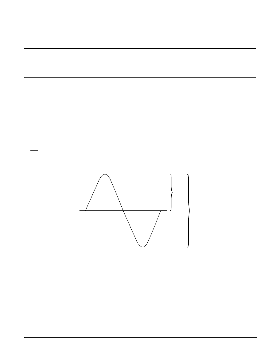
Mathematically, the RMS value is calculated at 0.707 times the peak value. When the RMS value is known, the peak
voltage and the peak-to-peak voltage can be easily calculated (as shown in the above diagram).
This information has a direct bearing on the oscilloscope display. Instead of seeing a voltage waveform of 120v on the
O‘scope screen, the technician will see a sine wave which is over 339 volts from the top most crest to the bottom most
point. This can be very confusing for a first time oscilloscope user especially when trying to view a very small PCC signal,
which is often less than one 12,000th the size of the 339 volt, peak-to-peak, 60Hz sine wave.
(Page 73, PCC Reference Manual)
120V
120 VAC = 120 VAC RMS
= 169.68 V. PEAK
= 339.36 V. PEAK - PEAK
169.68vp
339.36 vpp