Serial port, Com serial port connector (rj45) – ADLINK aTCA-6155 User Manual
Page 37
Functional Description
23
aTCA-6155
Serial Port
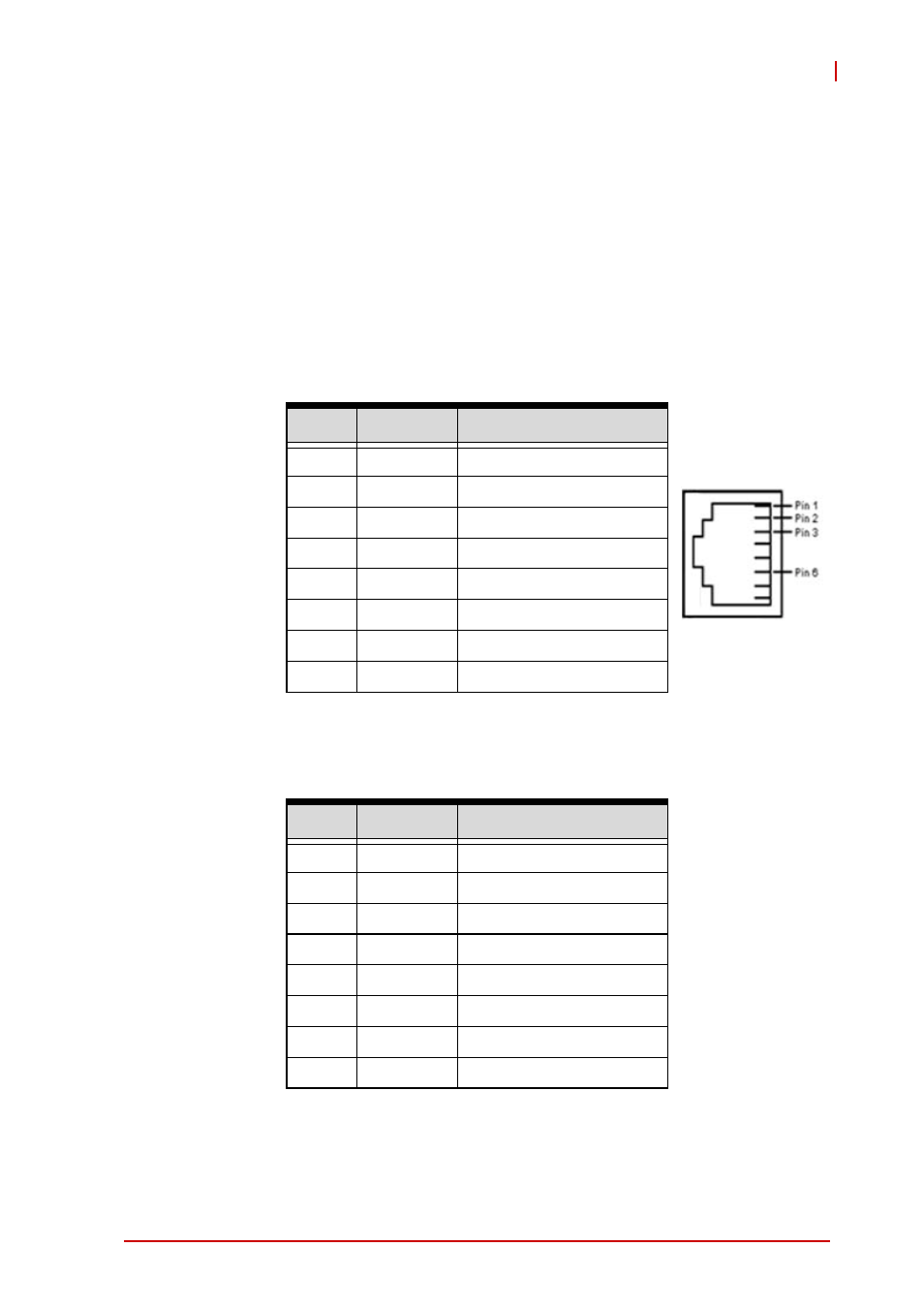
One PC-compatible serial RS-232, RJ45 port is provided on the
front panel with DIP switches SWX1 and SWX2 on the board that
are used to set the COM port function to RS-232 mode or IPMC
debug mode. A complete set of handshaking and modem control
signals are supported, with data transfer rates up to 115.2 kB/sec.
The Front Panel RJ45 COM connector CN8 pin-assignment is
listed below.
COM Serial Port Connector (RJ45)
Table 3-3: COM1 Serial Port Connector Pin Definition
When the Front Panel RJ45 COM connector is set to IPMC debug
mode, the pin assignment of the RJ45 connector is as below.
Table 3-4: IPMC Debug Port Connector Pin Definition
See “COM Mode Switch Settings (SWX1 and SWX2)” on page 26
for DIP switch settings.
Pin #
Signal
Function
1
DCD#
Data Carrier Detect
2
RTS#
Request to Send
3
DSR#
Data Set Ready
4
TXD
Transmit Data
5
RXD
Receive Data
6
GND
Ground
7
CTS#
Clear to Send
8
DTR#
Data Terminal Ready
Pin #
Signal
Function
1
NC
Not connected
2
NC
Not connected
3
NC
Not connected
4
DBG_TX
IPMC Transmit Data
5
DBG_RX
IPMC Receive Data
6
GND
Ground
7
NC
Not connected
8
NC
Not connected