ADLINK C485 User Manual
Page 48
42
• Expansion/Isolation Box User Guide
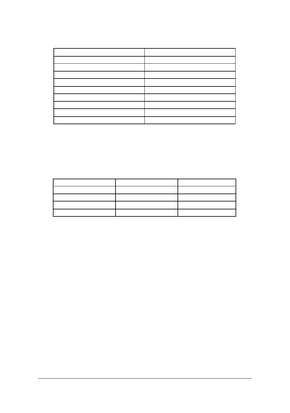
The pin definition for RS-422/485 DB25 male connector.
Pin No.
RS-422/485 Mode Signal Name
2
TXD+ (Out)
3
RXD+ (In)
4
RTS+ (Out)
5
CTS+ (In)
7
GND
13
RTS- (Out)
14
TXD- (Out)
16
RXD- (In)
19
CTS- (In)
RS-485 mode may let pin 2 and pin 3, pin 14 and pin 16 short together to
connect with other device.
We have 120-ohm terminator resistor built in each input signal pair. In
RS-485 mode, you may need to remove this terminator resistor.
Mode setting for C584XB/C588XB
DIP Switch Bit 1,3,5,7 DIP Switch Bit 2,4,6,8
Interface Mode
ON
ON
RS-232
ON
OFF
RS-232
OFF
ON
RS-422
OFF
OFF
RS-485
This manual is related to the following products:
See also other documents in the category ADLINK Hardware:
- USB-1901 (84 pages)
- USB-1210 (54 pages)
- USB-2401 (60 pages)
- USB-7230 (50 pages)
- USB-2405 (56 pages)
- DAQe-2010 (92 pages)
- DAQe-2204 (100 pages)
- DAQe-2213 (94 pages)
- DAQe-2501 (74 pages)
- PXI-2010 (84 pages)
- PXI-2020 (60 pages)
- PXI-2501 (62 pages)
- cPCI-9116 (98 pages)
- ACL-8112 Series (93 pages)
- ACL-8112 Series (94 pages)
- ACL-8112 Series (92 pages)
- ACL-8216 (75 pages)
- ACL-8111 (61 pages)
- PCM-9112+ (94 pages)
- PCM-9112+ (10 pages)
- cPCI-6216V (47 pages)
- ACL-6126 (28 pages)
- ACL-6128A (40 pages)
- PCM-6308V+ (52 pages)
- PCM-6308V+ (4 pages)
- PCI-7444 (82 pages)
- PCI-7434 (48 pages)
- PCI-7234 (56 pages)
- PCI-7260 (66 pages)
- PCI-7258 (38 pages)
- PCI-7256 (48 pages)
- PCI-7250 (48 pages)
- LPCI-7250 (48 pages)
- PCI-7396 (65 pages)
- PCI-7296 (59 pages)
- PCI-8554 (67 pages)
- PCIe-7360 (94 pages)
- PCIe-7350 (86 pages)
- PCIe-7300A (114 pages)
- PCIe-7200 (51 pages)
- PCI-7300A (112 pages)
- PCI-7300A (83 pages)
- PCI-7200 (96 pages)
- cPCI-7300 (83 pages)
- cPCI-7300 (82 pages)