2 timer/counter operation, 1 introduction, 2 general purpose timer/counter – ADLINK cPCI-7249R User Manual
Page 33
Operation Theorem
• 25
4.2 Timer/Counter
Operation
4.2.1 Introduction
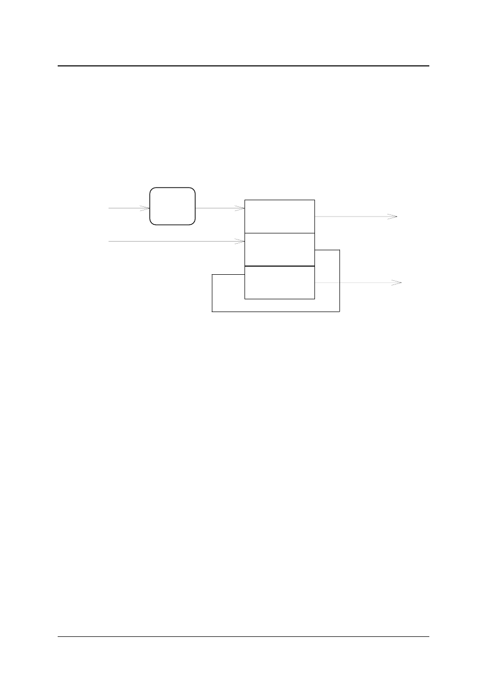
One 8254 programmable timer/counter chip is installed in 7248/96 series.
There are three counters in one 8254 chip and 6 possible operation modes
for each counter. The block diagram of the timer /counter system is shown in
Figure 4.2.
Event IRQ
Counter #0
2 MHz Clock
Timer #1
Timer IRQ
Timer #2
8254 Chip
C
G
C
G
C
G
O
O
O
'H'
'H'
'H'
Trigger
Edge
Control
P1C4
Figure 4.2 Timer/counter system of 7248/96 series.
The timer #1 and timer #2 of the 8254 chip are cascaded as a 32-bit
programmable timer. In software library, the timer #1 and #2 are always set
as mode 2 (rate generator).
In software library, the counter #0 is used as an event counter, that is,
interrupt on terminal count of 8254 mode 0 . Please refer to chapter 5 for
programming the timer/counter functions.
4.2.2 General Purpose Timer/Counter
The counter 0 is a general purpose timer/counter for users applications. It
can be used as an event counter, or used for measuring frequency, or other
functions. The following Mode are provided by the 82C54 chip.
z
Mode 0: Interrupt on Terminal Count
z
Mode 1: Programmable One-Shot.
z
Mode 2: Rate Generator.
z
Mode 3: Square Wave Rate Generator.
z
Mode 4: Software Triggered Strobe.
z
Mode 5: Hardware Triggered Strobe.