ADLINK ACL-6126 User Manual
Page 14
8 • Installation
2.4 Jumper and DIP Switch Description
You can configure the output of each channel and base address by
setting jumpers and DIP switches on the ACL-6126. The card's jumpers
and switches are preset at the factory. Under normal circumstances,
you should not need to change the jumper settings.
A jumper switch is closed (sometimes referred to as "shorted") with the
plastic cap inserted over two pins of the jumper. A jumper is open with
the plastic cap inserted over one or no pin(s) of the jumper.
2.5 Base Address Setting
The ACL-6126 requires 16 consecutive address locations in I/O
address space. The base address of the ACL-6126 is restricted by the
following conditions.
1. The base address must be within the range 200hex to 3F0hex.
2. The base address should not conflict with any PC reserved I/O
address. See Appendix A.
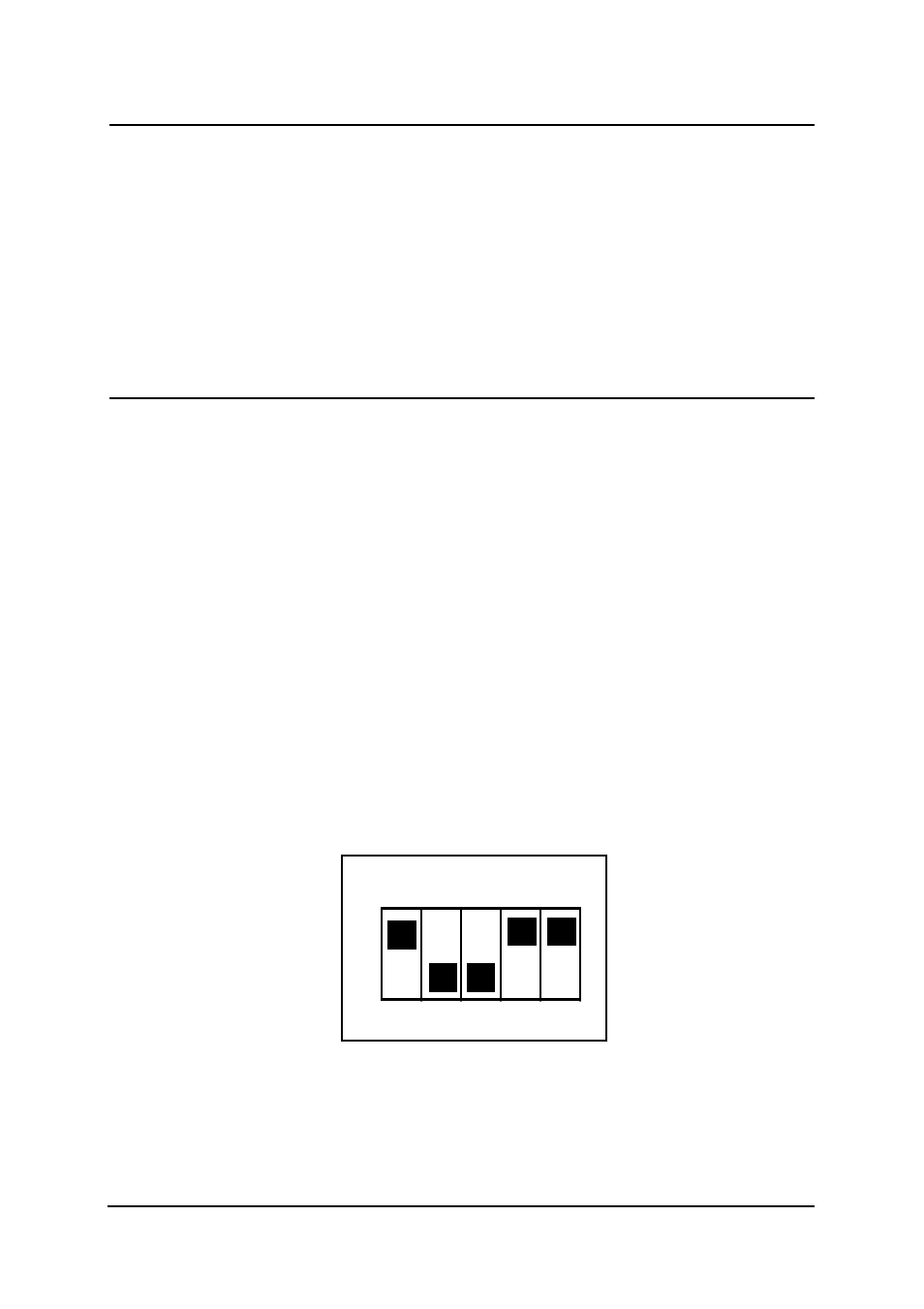
The ACL-6126's I/O port base address is selectable by an 5 position
DIP switch SW1 ( refer to Table 2.1). The address settings for I/O port
from Hex 200 to Hex 3F0 is described in Table 2.2 below. The default
base address of your ACL-6126 is set to hex 2C0 in the factory( see
Figure 2.2).
SW1 : Base Address = 0x2C0
1
2
3
4
5
ON
A ( 8 7 6 5 4 )
Figure 2.2 Default Base Address Setting