5 timer / counter connection, Counter 0 counter 1 counter 2, 8254 timer/counter – ADLINK ACL-8112 Series User Manual
Page 37
Signal Connections
• 29
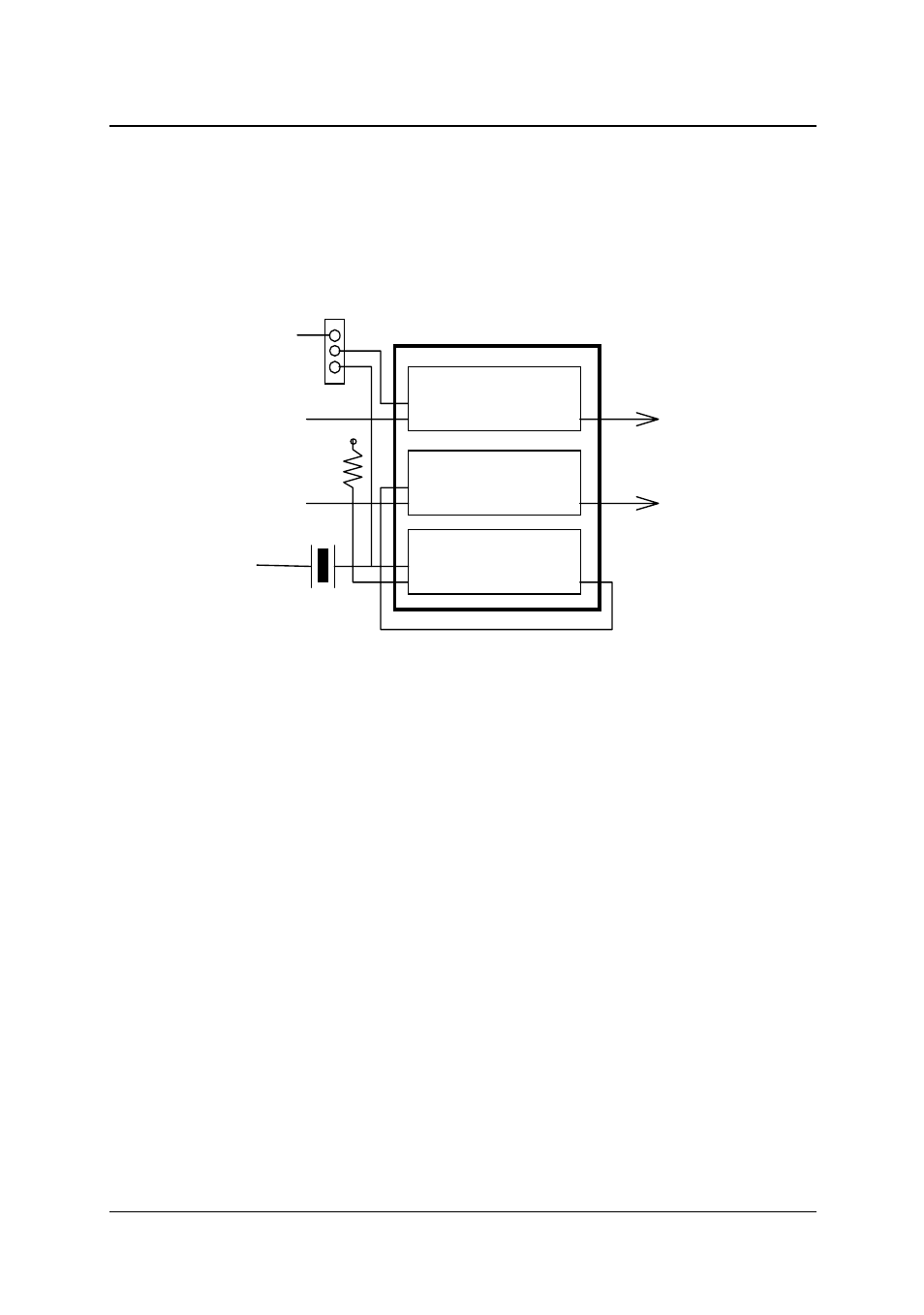
3.5 Timer / Counter Connection
The ACL-8112 has an interval 8254 timer/counter on board. It offers 3
independent 16-bit programmable down counters; counter 1 and counter 2
are cascaded together as a timer pacer trigger for A/D conversions and
counter 0 is free for user applications. Figure 3.10 shows the 8254
timer/counter connection.
Counter 0
Counter 1
Counter 2
CLK0
GATE0
OUT0
CLK1
GATE1
CLK2
GATE2
OUT1
OUT2
2MHz
Oscillator
Vcc
A/D Trigger
CN3 Pin-34
CN3 Pin-37
CN3 Pin-33
CN3 Pin-16
CN3 Pin-35
INT
EXT
8254 Timer/Counter
Figure 3.10 Block Diagram of 8254 Timer/Counter
The clock source of counter 0 can be internal or external, with the gate
being controlled externally and the output sent to CN3. As for counter 1
and counter 2, the clock source is internally fixed, while the gate can be
controlled externally and the output sent to CN3 too. All timer/counter
signals are TTL compatible.