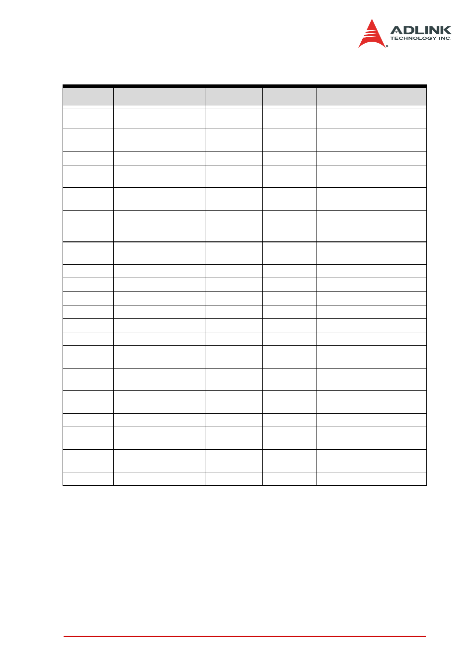
Table 3-2: vhdci-type (68-pin) connector legend, Legend, Signal connections 19 – ADLINK DAQe-2502 User Manual
Page 29: Pin # signal name reference direction description
Signal Connections
19
Legend:
*PIO means Programmable Input/Output
Pin #
Signal Name
Reference Direction
Description
1~4
AO_<0..3>
AGND
Output
Voltage output of DA channel
<0..3>
5
AOEXTREF_A/AI_0
AGND
Input
External reference for AO
channel <0..3> / AI input 2
6
AI_1
AGND
Input
AI input 0
7
EXTATRIG/AI_2
AGND
Input
External analog trigger / AI
input 1
8
AOEXTREF_B/AI_3
AGND
Input
External reference for AO
channel <4..7> / AI input 3
9~12
AO_<4..7>/AI_<4..7>
AGND
Output/Input
Voltage output of DA channel
<4..7> / AI channel <4..7>
(only for DAQ-2501)
13,14
AO_TRIG_OUT_
DGND
Output
AO trigger signal for channel
<0..3> <4..7>
15,16
GPTC<0,1>_SRC
DGND
Input
Source of GPTC<0,1>
17,51
GPTC<0,1>_GATE
DGND
Input
Gate of GPTC<0,1>
18,52
GPTC<0,1>_OUT
DGND
Input
Output of GPTC<0,1>
19,53
GPTC<0,1>_UPDOWN
DGND
Input
Up/Down of GPTC<0,1>
20
RESERVED
—
—
Reserved Pin
21,55
AFI<1,0>
DGND
Input
Auxiliary Function Input
,22,56,23,57
,24,58,25,59
PB<7,0>
DGND
PIO*
Programmable DIO of 8255
Port B
26,60,27,61,
29,63,30,64
PC<7,0>
DGND
PIO*
Programmable DIO of 8255
Port C
31,65,32,66,
33,67,34,68
PA<7,0>
DGND
PIO*
Programmable DIO of 8255
Port A
35~46
AGND
—
—
Analog ground
47,48
EXTWFTRIG_
DGND
Input
External waveform trigger for
AO channel <0..3> <4..7>
49
VCC
DGND
Power
(Output)
+5V Power Source
28,50,54,62
DGND
—
—
Digital ground
Table 3-2: VHDCI-type (68-pin) Connector Legend