Iepe input, 2 ai data format, Ai data format – ADLINK USB-2405 User Manual
Page 39: Figure 3-3, Excitation current for iepe sensor measurement
Operation
29
USB-2405
the signal is important. When AC coupling is selected, DC offset
present in the input signal is removed. AC coupling configuration
is indicated when the DC content of the input signals is to be
rejected. AC coupling enables a high pass R-C filter through the
input signal path, with corner frequency (-3dB) about 0.4 Hz.
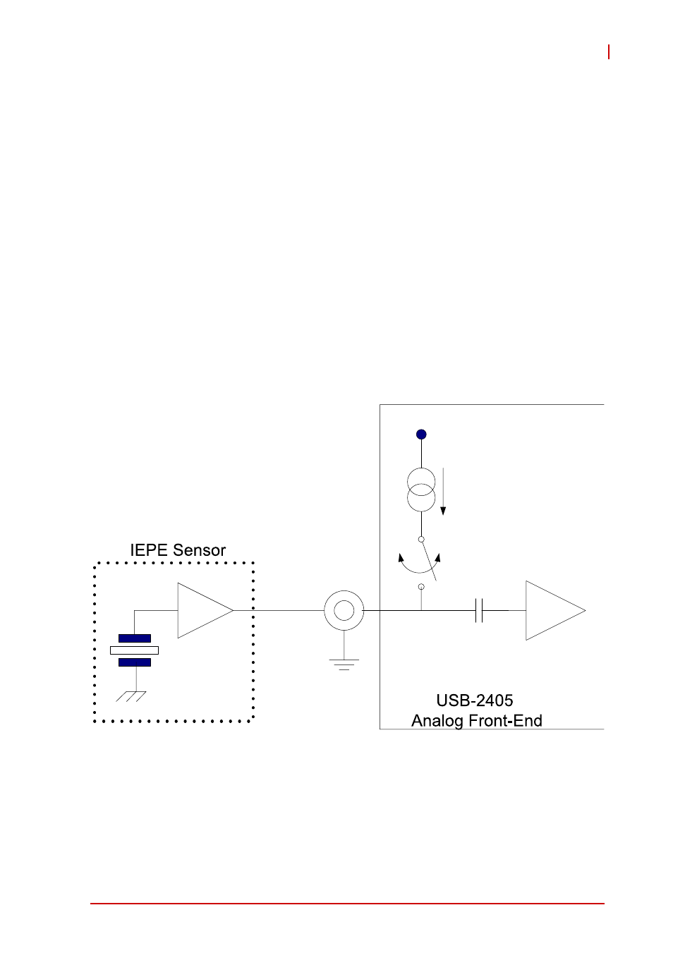
IEPE Input
For applications utilizing sensors such as accelerometers or
microphones, the USB-2405 provides an excitation current
source.
The excitation current is 2 mA for the IEPE sensors, with DC volt-
age offset generated because of the excitation current and sensor
impedance. When enabling IEPE current sources, the USB-2405
automatically sets input configuration to AC coupling.
Figure 3-3: Excitation Current for IEPE Sensor Measurement
3.2.2
AI Data Format
When an A/D converter is used, properties of the signal to be
measured must be ascertained to determine the channel to be
2mA
Constant
Current
VCC
IEPE ON/
OFF
AI Channel