2 analog input, 1 analog input front end configuration, Input coupling – ADLINK USB-2405 User Manual
Page 38: Analog input, Analog input front end configuration, Figure 3-2, Usb-2405 analog front end
28
Operation
3.2
Analog Input
3.2.1
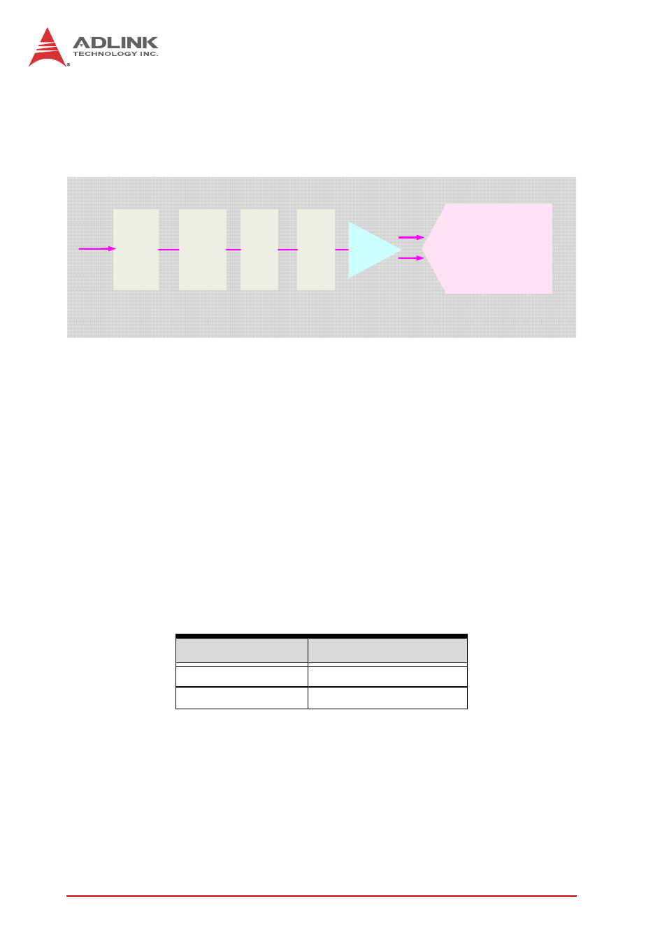
Analog Input Front End Configuration
Figure 3-2: USB-2405 Analog Front End
Input Configuration: Differential/Pseudo-Differential
Differential input mode provides anode and cathode inputs of the
BNC connector that respond to signal voltage differences
therebetween. If the signal source is ground-referenced, the
differential input mode can be used for common-mode noise
rejection.
If the signal source is a floating signal, setting pseudo-differential
input mode will provide a reference ground connected to the
cathode input of the BNC through a 20 kΩ resistor.
Recommended configurations for the signal sources are as
follows.
Table 3-1: Signal Source-Card Configuration
Input Coupling
When DC coupling is selected, DC offset present in the input sig-
nal is passed to ADC. DC coupling configuration is indicated when
the signal source has a small offset voltage or if the DC content of
Signal Source
Card Configuration
Floating
Pseudo-differential
Ground-reference
Differential
Calibration
Circuit
24 Bit ADC
AI
IEPE
Circuit
AC
Coupling
circuit
Diff input
ADC Driver
Differential/
Psuedo-
differential
Switch
Circuit