Venting installation instructions – Desa (V)T32EN-A Series User Manual
Page 12
12
www.desatech.com
116647-01A
INSTALLATION FOR VERTICAL TERMINATION
Note:
Vertical restrictor must be installed in all vertical installations.
1. Determine the route your vertical venting will take. If ceiling
joists, roof rafters or other framing will obstruct the venting
system, consider an offset (see Figure 19) to avoid cutting
load bearing members. Note: Pay special attention to these
installation instructions for required clearances (air space)
to combustibles when passing through ceilings, walls, roofs,
enclosures, attic rafters, etc. Do not pack air spaces with insu-
lation. Also note maximum vertical rise of the venting system
and any maximum horizontal offset limitations.
2. Set the fireplace in desired location. Drop a plumb line down
from the ceiling to the position of the fireplace exit flue. Mark
the center point where the vent will penetrate the ceiling. Drill
a small locating hole at this point.
Drop a plumb line from the inside of the roof to the locating
hole in the ceiling. Mark the center point where the vent will
penetrate the roof. Drill a small locating hole at this point.
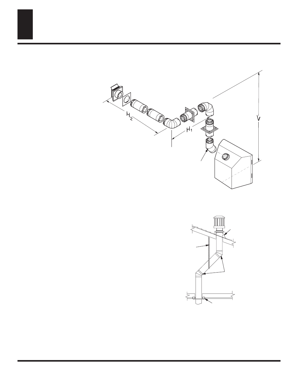
Figure 19 - Offset with Wall Strap and 45° Elbows
Figure 18 - Horizontal Termination Configuration for Venting Using Two 90° Elbows with Termination at 90° with Fireplace
VENTING INSTALLATION
INSTRUCTIONS
Continued
VENTING INSTALLATION INSTRUCTIONS
Installation Planning (Cont.)
Installation for Vertical Termination
Venting with Two 90° Elbows
Horizontal (H
1
) +
Vertical (V)
Horizontal (H
2
)
5' min.
6' max.
6' min.
12' max.
7' min.
18' max.
8' min.
20' max.
20' max.
20' max.
45° Elbow
45° Elbow
Wall Strap
Roof Flashing
Ceiling Firestop