Setting up the system, 7 setting up the system, English – Denon AVR-2801 User Manual
Page 14
ENGLISH
14
TUNING
BAND
TITLE
MENU/GUIDE
MODE
MEMORY
USE/LEARN T.TONE
RETURN
DVD
SET UP
STATUS
DISPLAY
ON SCREEN
MUTING
AVR/AVC
VIDEO
DVD
TV
AUDIO
VDP
VCR
CD
CDR/MD
DECK
SYSTEM
SETUP
SURROUND
PARAMETER
CH SELECT
SELECT
ENTER
7 SETTING UP THE SYSTEM
• Once all connections with other AV components have been completed as described in “CONNECTIONS” (see pages 6 to 11), make the various
settings described below on the monitor screen using the AVR-2801/981’s on-screen display function.
These settings are required to set up the listening room’s AV system centered around the AVR-2801/981.
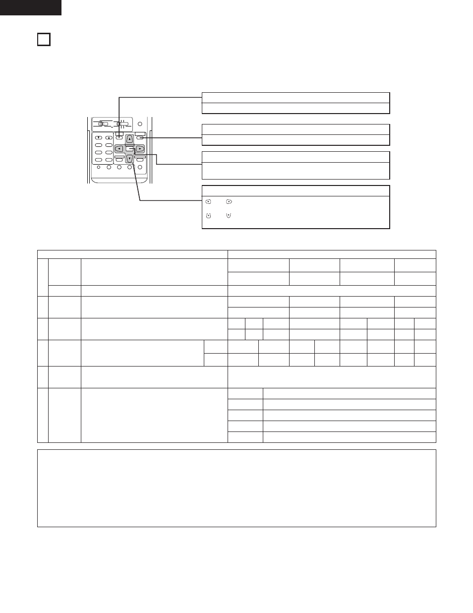
• Use the following buttons to set up the system:
SYSTEM SETUP button
Press this to display the system setup menu.
SURROUND PARAMETER button
Press this to display the surround parameter menu.
ENTER button
Press this to switch the display on the screen.
Also use this button to complete the setting on the screen.
CURSOR buttons
and
: Use these to move the cursors (
0
and
1
) to the left and right
on the screen.
and
: Use these to move the cursors (• and ª) up and down on the
screen.
• System setup items and default values (set upon shipment from the factory)
System setup
Default settings
q
w
e
r
t
y
Speaker
Configuration
Subwoofer mode
Delay Time
Channel
Level
Digital In
Adjutment
On Screen
Display
Auto Tuner
Presets
Input the combination of speakers in your system and their
corresponding sizes (SMALL for regular speakers, LARGE for full-size,
full-range) to automatically set the composition of the signals output
from the speakers and the frequency response.
This selects the subwoofer speaker for playing deep bass signals.
This parameter is for optimizing the timing with which the audio
signals are produced from the speakers and subwoofer according to
the listening position.
This adjusts the volume of the signals output from the speakers and
subwoofer for the different channels in order to obtain optimum
effects.
This assigns the digital input jacks for the different input
sources.
This sets whether or not to display the on-screen display that appears
on the monitor screen when the controls on the remote control unit or
main unit are operated (from MONITOR outputs only).
FM stations are received automatically and stored in the memory.
Input
source
Digital
Inputs
Front Sp.
Center Sp.
Surround Sp.
Subwoofer
Small
Center
3.6 m (12 ft)
Surround L & R
—
3.0 m (10 ft)
—
Small
Yes
Large
LFE
Front & Subwoofer
3.6 m (12 ft)
Front L
0 dB
CD
COAXIAL
On Screen Display = ON
A1 ~ A8
B1 ~ B8
C1 ~ C8
D1 ~ D8
E1 ~ E8
87.5/89.1/98.1/107.9/90.1/90.1/90.1/90.1 MHz
520/600/1000/1400/1500/1710 kHz/90.1/90.1 MHz
90.1 MHz
90.1 MHz
90.1 MHz
Front R
0 dB
DVD
OPTICAL 1
Subwoofer
0 dB
VDP
OPTICAL 2
TV/DBS
OPTICAL 3
VCR-1
OFF
VCR-2/
V. AUX
—
—
OFF
—
—
Center
0 dB
Surround L
0 dB
Surround R
—
—
0 dB
—
—
NOTES:
• The on-screen display signals are output with priority to the S-VIDEO MONITOR OUT jack during playback of a video component. For example,
if the TV monitor is connected to both the AVR-2801/981’s S-Video and video monitor output jacks and signals are input to the AVR-2801/981
from a video source (VDP, etc.) connected to both the S-Video and video input jacks, the on-screen display signals are output with priority to
the S-Video monitor output. If you wish to output the signals to the video monitor output jack, do not connect a cord to the S-VIDEO
MONITOR OUT jack. (For details, see page 22.)
• The AVR-2801/981’s on-screen display function is designed for use with high resolution monitor TVs, so it may be difficult to read small
characters on TVs with small screens or low resolutions.
• The setup menu is not displayed when “HEADPHONE ONLY” is selected.