Page 25 – DoorKing 1820 User Manual
Page 25
DOORKING, INC., INGLEWOOD, CA 90301
Date:
Dwg. No.
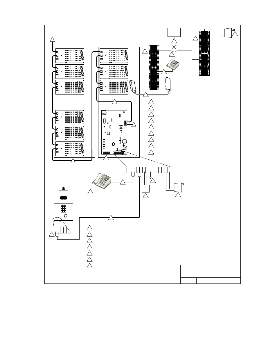
1820 Telephone Intercom System
Wiring Detail for Dual RJ-71C Option
Rev.
Title:
4/05
A
M1820-065-9
17
21
15
14
13
20
19
18
11 12
16
23 24
22
1820 Telephone Intercom System
Wiring Detail - Dual RJ-71C Option
C.O.
PHN
16 VAC
PWR
INPUT
7
8
3
1
2
5
Lobby Panel
4
3
1 2
2
Earth Ground.
3
Optional Central Office phone line - touch tone, loop start.
4
Doorman / Concierge Telephone (Optional).
5
Lobby panel. Connect additional lobby panels in parallel. Refer to lobby panel installation manual for
additional wiring requirements.
6
Use twisted pair wires for phone connections. 24 AWG up to 800 feet; 22 AWG up to 1600 feet.
7
8
RJ71C phone block. See drawing M1816-065-6 for detail.
9
Incoming phone lines from Central Office.
10
Outgoing phone lines to individual apartments.
11
DoorKing connecting cable.
12
RS-485 connecting cable.
13
To additional Line Interface Boards.
Decoder board terminals. Used with 1816 systems only.
13
12
12
13
12 VDC
Reg
Input
14
14
Powered RJ-71C phone block P/N 1820-047 for use only with residents
without active Central Office phone service.
15
15
12 VDC Regulated power supply.
Resident
Telephone
without
C.O. Line
11
10
INCOMING
C.O. PHN
LINES
9
16
16
Disconnect the resident’s line form the phone company. Connect from
powered RJ-71C to resident’s terminals.
16 Volt, 50 VA UL Listed Transformer.
1
Doorman Telephone
4
6
6
1820-065-B-2-06
Page
25