5« standard installation fai*cdrttractor, General installation information, 2 place of installation – STIEBEL ELTRON DHE 18 SLI 25 A User Manual
Page 29: 3 equipment preparation for installation, Brackettn, 5 trimming the power cable to size, 6 ^uipment installation, 7 water connection (s, 8 electrical connection, 9 completing the installation
Attention! The text in this document has been recognized automatically. To view the original document, you can use the "Original mode".
STIEBEL ELTRON
5« Standard installation fai*CDrttractor&
E lectrical: unfinished w alls-from below :
w ater: unfinished w alls
Key eo figures . [^
1 U se'i'terfice
2 E qubner:t cip
3 B asC i b^ck v\v.l
4 I5I V V (om prxrsiion ii I 'nj^
5 C ok w :iter cc'iip essio'- Iting
6 C a:»!e gronrrist ielectn«.! sup^lv ca:>l8
fen oelovv'
7 M?.ins ■erTriin?.!
8
lo|),
•yni 'i wn
I
9
E lectronics
10
vw 'li !-(A l i)-.vilh nnci-xjilon
11
sysien
12 Flaw 'ate rrstf-sunn« ip Fill
13 iiocc:! i:r st:l
vh
u:: krtn'-diKor
14 L: D c cstic' 'tr<'.ltk lights'
15 I i>: ns^ lo^k
16 S et V A u& •tr<’.nsducer c^ib e plug
17 S afety t'S H Tial cut out (S TB )
ia O ijik ^(¡•••■ioriN IC )
19 S '<*.p-i' tsib •or sub-r<*.ck (se vice)
20 U I H .iric |!
h
I
c
21 M ounting oividtje:
22 S t'v.i'er ir. the cold w T O r corrio'ession •'fc'n?
23 lilii-c
♦
LED diiignostic ^traffic Lights''
red illurm nales in ciise of fjulls____
io»o VC Ho
appliance Is heating water_______
flashing: T he appliance Is upplicd
,reen \»i'ith powftr___________________
General installation
information
The e<]uipm cnc is prepared at the fac*
eory for standard instaliaeion (see figs.
» ln5ttf.ll*tion a:»ovs a w orktop [C ] (a).
» W ater cc'f.sc:ion. tnfinished w *l
s,
con
oression ftd'j? [G ] (4 *nd 5).
» E lectr'ea' connect c '. unfi ' is 'ed w a Is. i'
t*:e low e'eq^iprrisrr; a'sa E l6).
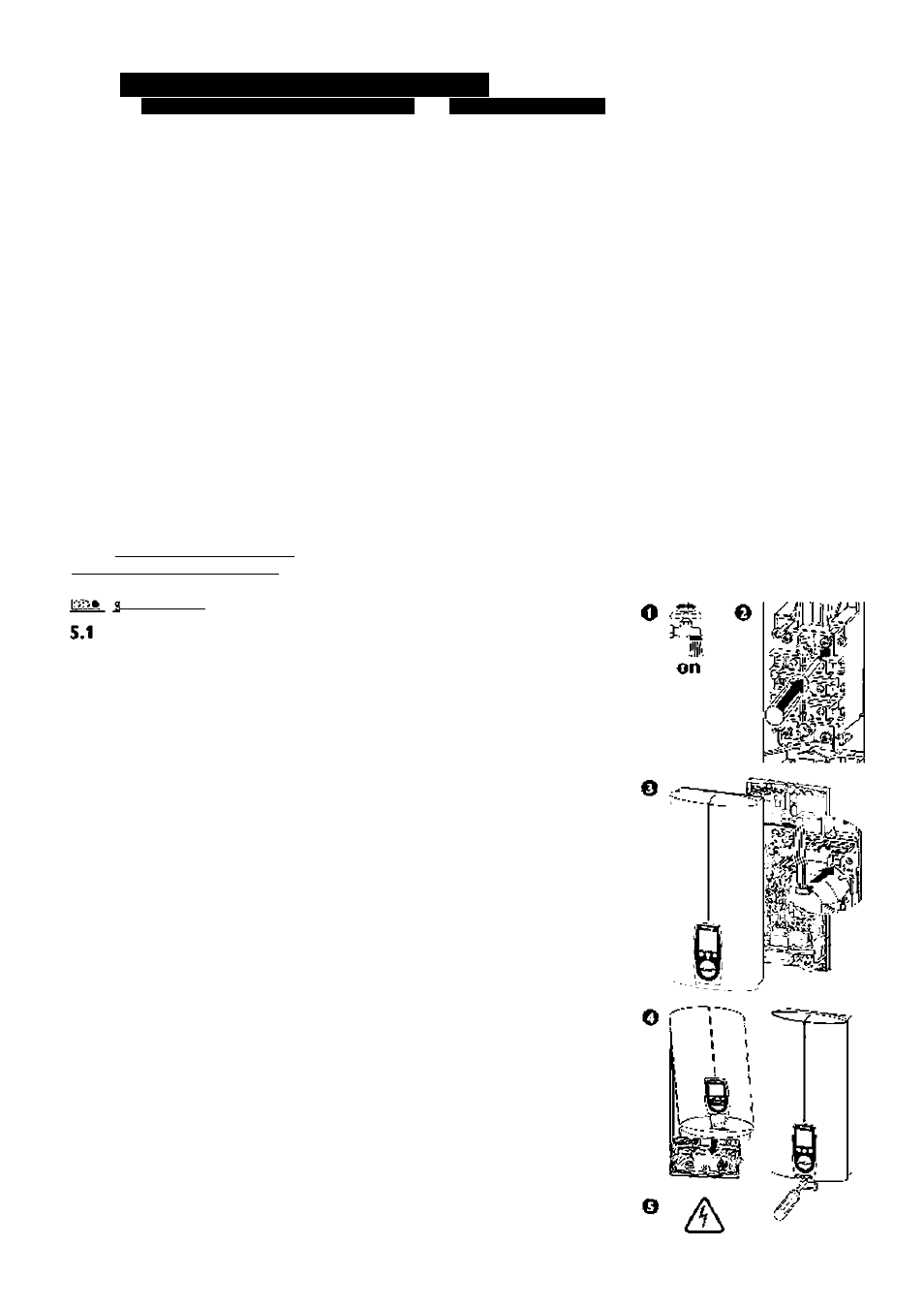
» O irput 21 5.2 Place of installation hjtal the D hE ve'tca'Iy in *ccorc*nce w t' Q C j (a ¿ bovs or b be'cw w orkic?) in * fx):rn rx)rv Ihc nsk ol irxK .. 5.3 Equipment preparation for installation • O pen t'e eq^ipm eir ^; a P ul ihe fl:ip •brvvarc. b O pen t'e 'kp dc*.v'w a ds. c R tleast the fxing sc'ew s. d R tnov« the equiiire't cai. • K::novf: Ific Iwc-; wh II I jhs :: E • » l’fx:S '< i lrv.vn 1)0’•• V H |)- n I h )>. b K::inovo liic wh II I jhs :: ';y |!••ll iij; lorw H 'xl'- » R sno^e the f.>:in§ togg s E (IS ;. 5.4 5ecurin^i bracketTn • M a k ou: the fxing holes rb ■ the rioun- tng or<*.cltje: using the institit’c' tenpU te • ?i(:c..r;: Ihf: •nounli' c -.vilh / S tfx;»v> H '-:f I »A -i :)kic-, fn:>l '>u:)|)li:.:(l: Securing the mounting sdcd'rvi I lo l;:c ::l I":: '::l(W rtnl v .-' h II). 5.5 Trimming the power cable to size Iri n l"(: Ixj'A-x:'(’«•)!(: lo xi/o in «rcorxrrtnco v/i h J4j. N ote: 'c ■ ¡'•st!tl ing t'e pow er ctble. 5.6 ^uipment installation » R c.,t€ t's pow er c?.ble t'ro.,gh t*:« ca:»le gronne: i6; a'd oress the baci.w all eve.' » Ft the eiuip nsnt, seu.i'e the ixi'g toggle i1 S ). 5.7 Water connection (S l.'nportnt in'biTn;ition: Thoroughly flush the cold-w atc.' sup- ply pipes. A lw ays incorporacc the strainer and fiuir\g supplied (22 and 23. bag on the colcl*w acer fitting) into die col-J-water' compression fit ting. Wfien nepl:icingt!ie insttllnion,c!ieck ciiat the strainer' is in place. M ove.' use the: chroo-w ay shuc-off valve (5) 5.8 Electrical connection Cc"&c: the e ectrkal suoply caole to the ter- ^ Important information: The protection level IP 25 (hose- ¿.L j prooO can only be ensured w ich a cor rectly fitted cable grom m et i6) and seal 5.9 Completing the installation 1 . 0|:<;" ,h:.: lfirx;(;--.v>iy •>h..l-o"valv:: 2. i;i ■••::f:«rk wxl f:,?^(:E(3). (S). 5.10 Initial start-up (oi'ily l)V A (';jxliilC(l roi'.'rHv'lor) o Fill and vent chc equipm ent. P lease note: risk of running dryl O pen and close all connected draw -off been purged from the pipew ork and the equipm ent. seeM .2 Im portant in* o Activate the safety pressure limiter. The DHE...SL! elecuonic comfort is supplied with the safe^ piessure limiter (AE 3) in stripped state (press t!ie reset button). 0 P ush set value transducer cable plug onto the P C B . Fit the equipment cap and secure with the screw. o S w itch on the m ains pow er. Check the instantaneous v/ater heater function. e R em ove the proeeccive film from the user interface. E quipm ent handover • M a' (scald ng). » H *nd eve'these inm r'uctions to the user for safekeeping. on 7}
supplied.
C ao (a) shouk be used as <*.n <*.id
the t'reaced 5t.,ds of the nounting b-'a-
eke:.
CO reduce ebe: flow rate:.
irinal St ip (seeWiring dbgrair
on the cable bush.
C onnect the equipm ent to earth.
valves several tim es, until the air has
form ation".
E xpdn t'fe ec^ipm ent fij'ctb' to the ^ser
¡m e •am i ia'isethe user w t' its oper