Wiring schematic – Autostart AS-1755V User Manual
Page 4
Attention! The text in this document has been recognized automatically. To view the original document, you can use the "Original mode".
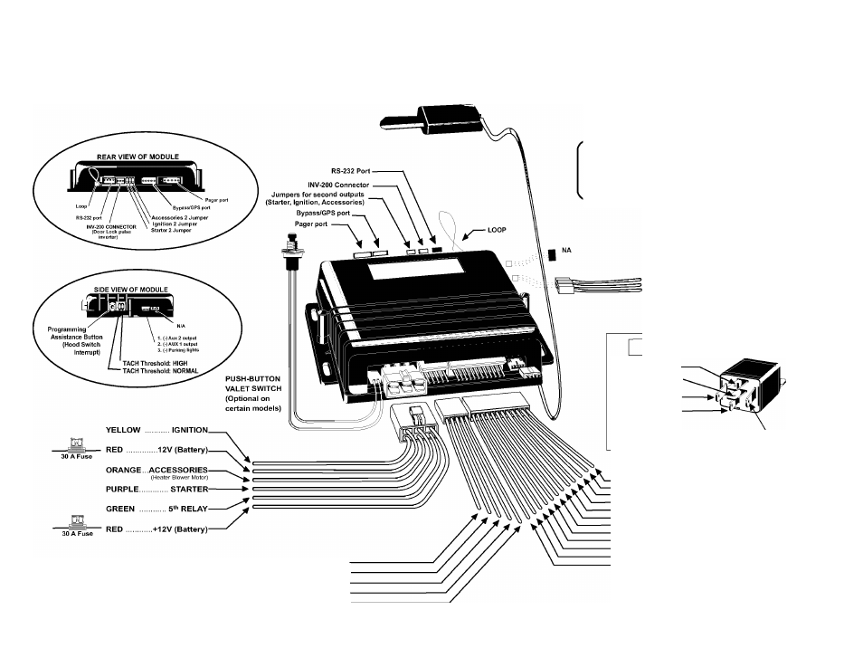
WIRING SCHEMATIC
For Automatic Transmissions:
Cut the yellow loop before plugging
in the module.
Note:
This product supports the Trilogix bypass.
To program the Trilogix bypass to the Autostart remote
starter, please ensure that the Trilogix bypass and the
Autostart starter are powered up simultaneously.
3. YELLOW/WHITE....... (-) PARKING LIGHTS
2. BLUE/WHITE ... (-) AUX 1 output
1. GRAY/LIGHT BLUE ... (-) AUX 2 output
Optional Starter Kill Relay
N/A87
STARTER WIRE 87A
(Solenoid Side)
IGNITION (+) 85
STARTER WIRE 30
(Key Side)
86
Start Kill Output (-)
1- BLACK................................GROUND (-)
2- PURPLE.................................. TACH (AC)-
3- GREY...................... HOOD SWITCH (-)
4- ORANGE ............ BRAKE SWITCH (+) .
5- YELLOW........... PARKING LIGHTS (+) .
12- YELLOW.................................. (+) Glow plug input
11- GREY....................................... (-) NEG. Door input
10- WHITE.......................................(-) GROUND when running
9- PURPLE.................................... (-) EXT. TRIGGER input
8- ORANGE................................... (-) Parking Brakes input
7- WHITE/ORANGE........................ (-) Starter kill output
6- BLUE/WHITE.............................. (+) POS. Door input
5- WHITE/GREEN........................... (-) DISARM
4- WHITE/BROWN.......................... (-) REARM
3- GREEN ...................................... (-) UNLOCK
2- BROWN ..................................... (-) LOCK
1- BLUE ........................................ (-) TRUNK
V1.00 MO - Jan. 16, 2008
15 A Fuse