Air evacuation, Drying times and energy consumption, Connection to a ventiiation duct – ASKO 7005 User Manual
Page 7: Specification
Attention! The text in this document has been recognized automatically. To view the original document, you can use the "Original mode".
Specification
Height
32 1/4" (820 mm)
Width
23 1/2" (595 mm) +
exhaust hose
connection
Depth
23 1/2" (595 mm),
including controi
panel and program
knob
Depth - Door open
46“ (1170 mm)
Weight
86 lbs. (39 kg)
Speed
52 rpm
Drum materiai
Stainless steel
Outer casing
Galvanised steel
sheet
Instaiiation
Free-standing, buiid-
in or on top of a
washing machine
Power requirement
3150 W
For connection
Doubie-phase,
208-240 V , 3 0 A
Internai fuse
15A
Power requirement
3150 W
Air evacuation
The air evacuation can be connected at the
rear. When the machine is belvered, one
the rear is open.
T rio tumble dryer is supplied with a stub
pipe, A UL-CSA hose must be supplied by
the consumer or installer.
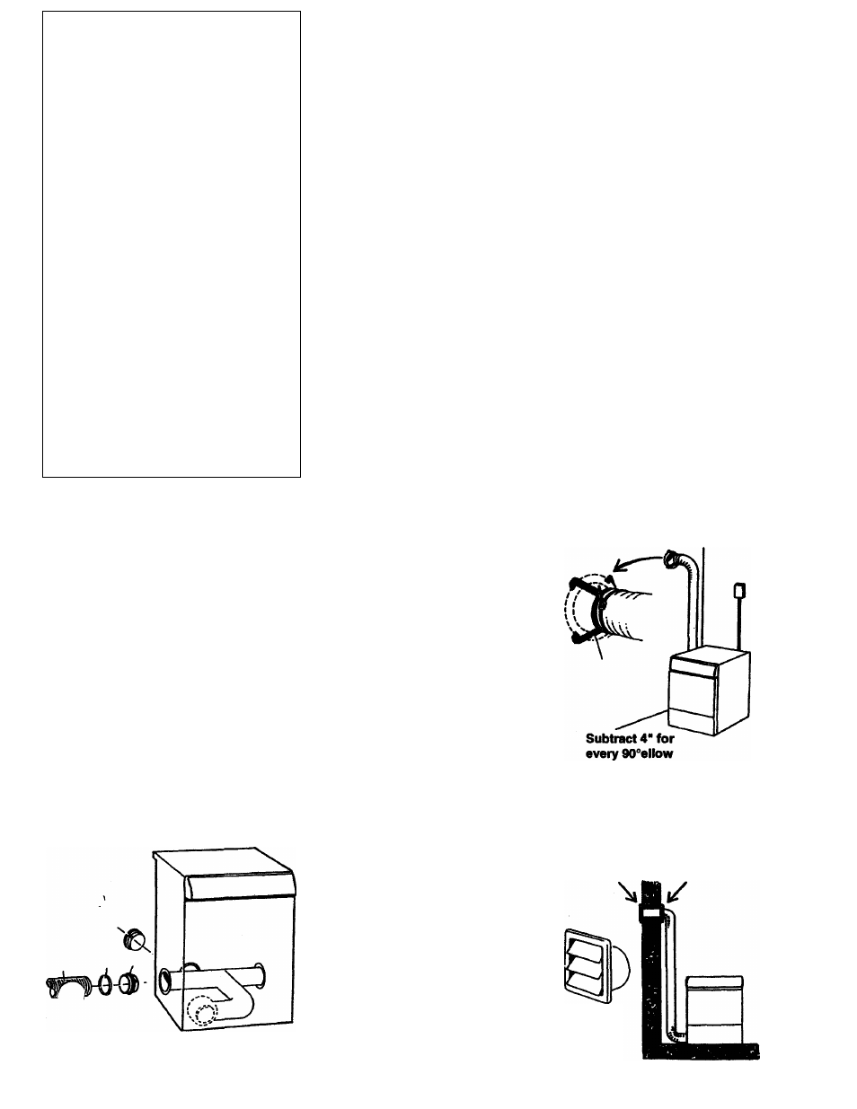
Fit the air evacuation as foiiows:
• Push the hose onto the stub pipe and
fasten a clamp.
• Insert the stub pipe with the hose into the
hole.
WARNING - To reduce the risk of fire, this
appliarwe MUST BE EXHAUSTED
OUTDOORS or the equivalent.
Drying times and energy
consumption
Drying times and energy
consumption
The table below shows drying times
and energy consumption in
accordance with the following
conditions:
• Program 2 has been used (the
normal "Dry" automatic program).
• Drying temperature Normal
• Fabrics dried are of cotton,
previously spun at 800 r/min.
• The dryer is in a room with a
temperature of 20° C (68° F), and
the exhaust hose supplied with the
machine is in use.
Drying times
many factors, such as the
amount of washing, moisture
content, type of fabric, air
temperature and humidity.
Performance can also be
affected by how the machine
has been installed. Drying
time is also naturally affected
by how dry the washing is to
be when removed from the
machine.
Connection to a
ventiiation duct
Connect the exhaust hose to a ventilation
exhaust fitting or to a discharge through
the wall.
Secure the hose joint to the outlet stub on
the machine.
Run the hose with as few bends as
possible to the point of discharge. If
necessary, it can be extended to a
maximum of 22 feet erf 4" diameter hose.
Make any bends as gentle as possible. A
maximum of four 90° bends may be fitted
in the hose. The more bends and the
longer the hose, the less will be the
amount of air passing through the
machine.
If more than 22 feet of hose is needed,
diameter must be increased to 6* or 8".
If the hose is taken to a wall outlet, a
ventiiation grille should be fitted to prevent
reverse ftow of cold air.
IMPORTANTI
The appliance should not be exhausted
into a chimney, a wall, a ceiling, or a
concealed space of a buildirvg.
The only rigid of flexible metal duct should
be used for exhausting, unless the
appliance has been investigated for use
with nonmetallic duct.
Fit the ventilation
grille to the inside
or outside of the
wall
Ventilation
grille