Electrical connections, Warnins, Warning – ASKO T731 User Manual
Page 6
Attention! The text in this document has been recognized automatically. To view the original document, you can use the "Original mode".
ELECTRICAL CONNECTIONS
The power supply cord must be grounded. If the machine
Is to be used In a wet area, the supply must be protected
by a residual current device.
NOTE: In Canada, the dryer Is delivered ready-fitted with
a four-prong plug Intended for connection to a single
phase supply.
Connection to a permanently wired supply point must be
made only by a qualified electrician.
As supplied:
Single-phase, 230 V, 60 Hz,
2500 Watt heater rating
30 A fuse required
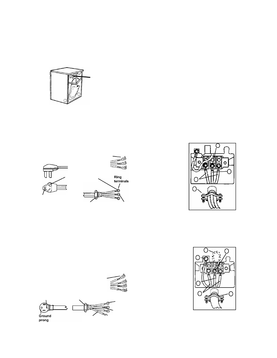
Remove cover to
access terminal box.
(Requires a 20-Torx
screwdriver.)
WARNINS:
The receptacle on the rear of the machine is
designed to accommodate ASKO washers
ONLY
(rated 208-240 V.) To use this receptacie, you must
use the ready-htted piug suppiied with the washing
machine or an equivaient. The suppiy connection
must be 208-240 V, 20 A.
ASKO washers rated 208-240 V have two internai
fuses of 15 A each.
CONNECTING A 3-WIRE POWER CORD
WARNING!
Before starting this procedure, be
sure the power is turned off at the breaker/fuse box.
Power Supply Cord
You will need a 3-wire power supply cord with three No.
10 copper wires and a matching 3-wire receptacle of
NEMAType 10-30R, as illustrated below:
3-WIRE CORD
Spade terminals
with upturned
This blade connects
to this conductor.
Neutral
3/4” UL-listed
strain relief
Neutral
(white)
1. Turn the power off at the breaker/fuse box.
2.
Remove terminal block cover.
3.
Use the strain relief attached below the terminal block
opening.
4.
Loosen or remove center terminal block screw.
5.
Connect neutral (white) wire of power supply cord
to the center, silver-
colored terminal block
screw.
Tighten
the
screw.
6.
Connect the other
wires to outer screws.
7. Tighten the strain relief
screws.
8.
Replace
terminal
box cover on back of
dryer.
9.
Plug dryer into wall
receptacle.
10.
Turn power on at
breaker/fuse box.
CONNECTING A 4-WIRE POWER CORD
WARNING!
Before starting this procedure, be
sure the power is turned off at the breaker/fuse box.
PowerSupply Cord
You will need a 4-wire powersupply cord with four No. 10
copper wires and a matching 4-wire receptacle of NEMA
Type 14-30R, as illustrated below. The fourth wire must
be identified with a green cover and the neutral conductor
by a white cover.
4-WiRE CORD
Neutral
Spade terminals
with upturned
3/4” UL-listed
strain relief
Ground
(green)
Ring
terminals
Neutral
(white)
1. Turn the power off at the breaker/fuse box.
2.
Remove terminal block cover.
3.
Use the strain relief attached below the terminal block
opening.
4.
Remove center terminal block screw.
5.
Remove ground wire
(green with yellow stripes)
from
external
ground
connector screw. Fasten
under center, silver-colored
terminal block screw.
6. Connect ground (green) wire
of cord to external ground
conductor screw.
7. Connect neutral (white) wire
of cord under center screw
ofterminal block.
8.
Connect the other wires
to outer screws.
9.
Tighten the strain relief
screws.
10. Replace terminal box cover on back of dryer.
11. Plug dryer into wall receptacle.
12. Turn power on at breaker/fuse box.
Page 6