American Dryer Corp. AD-385 User Manual
Page 24
Attention! The text in this document has been recognized automatically. To view the original document, you can use the "Original mode".
Providing local codes permit, power to the dryer can be made by the use of a flexible U.L.
listed cord/pigtail (wire size must conform to the rating of the dryer), or the dryer can be hard
wired directly to the service breaker. In ALL cases, a strain relief must be used where the wiring
enters the dryer and the service box.
A wire diagram is located inside the control box area for connections data.
1.) Single Phase (1 0) Model (Hookup) Connections
The electrical input connections to the dryer the two (2) power lead connections (LI and N
or L2) and the ground.
S/NGLE
PHASE 110) ELECTRICAL CONNECTIONS
60 HZ
50 Hz
ELECTRIC POWER
COWCCriCWS
ELECTRIC POWER CONNECTIONS
BLACK WHITE GREEN
BLACK RED GREEN
*
-
Olr
* -
0^
POSITIVE HEUTRAL GROUND
POSITIVE
neutral
ground
STUD
STUD
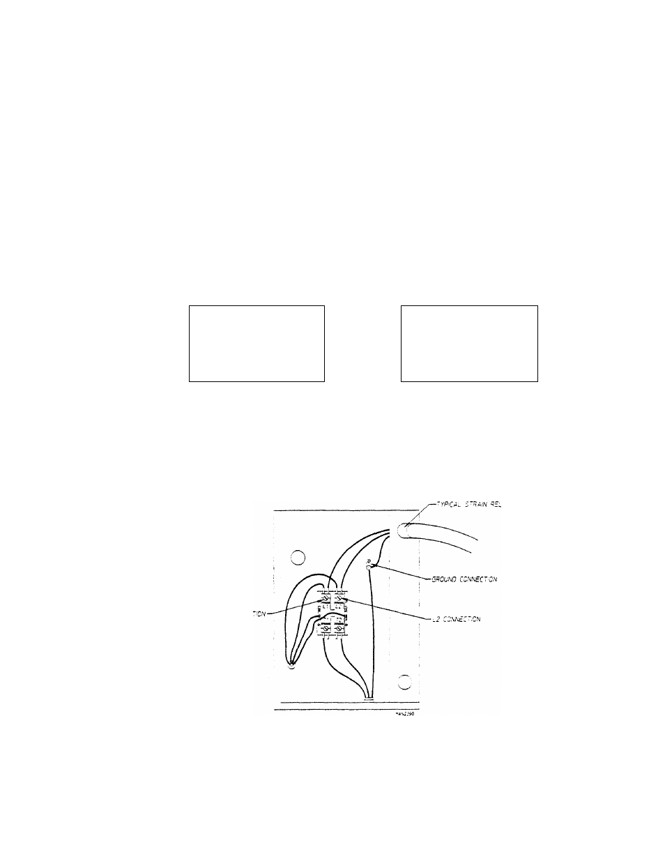
The two (2) power connections are made at the motor contactor (LI and L2 termination
points) located inside the electrical service box. The ground connection is made at the
ground lug also provided in this service box.
Providing local codes permit, power to the dryer can be made by the use of a flexible U.L.
listed cord/pigtail, or the dryer can be hard wired directly to the service breaker. In ALL
cases, a strain relief must be used where the wiring enters the dryer and service box.
20