Vom-78t operations manual – ASA Electronics Voyager VOM78T User Manual
Page 7
Attention! The text in this document has been recognized automatically. To view the original document, you can use the "Original mode".
VOM-78T OPERATIONS MANUAL
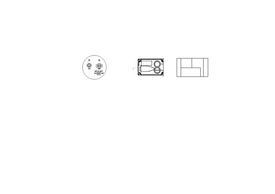
9. MIR/NOR OPTION
10
.
11
' Æ
IP '
PL
jpJ^
Monitor switch position in "MIR" position
Voyager camera switch
(magnet) in "MIR" position
Voyager Tiit camera
(VBCT-130)
■
This combination will result in an inverted (mirrored) image that is correct for rear (back-up) camera use.
■
If the opposite image is required for applications other then rear (back-up) camera use, either the monitor or the camera
switch should be set to the "NOR" position.
■
In case VBCT-130, Tilt camera applied to CA1 position, MIR / NOR option can be selected only by the CA1 dip switch
■
Make sure that monitor/camera switch settings are correct for your particular application.
AUDIO JACK
■
Connects audio connector to an (optional) external speaker.
CA1/CA2 INPUTS JACKS
- In single camera applications the camera should be connected to CA1 Monitor Input.
- A Rear/Back-up Camera should be connected to CA1 Monitor Input in any application.
Reverse trigger Feature
Applying +12 Volts to Blue/Reverse Trigger lead serves two functions:
1) Monitor comes ON from Stand-by mode and switches to CA1 input.
2) Monitor Input will switch from CA2 to CA1 while +12 Volts is applied.
6
Voyager