Figure 6: rs-485/422 wiring diagram (2 wire) -14 – Connect Tech JB2 User Manual
Page 34
4-14
Chapter 4: Appendices – RS-485/422 Interface
Titan/cPCI User’s Manual, ver. 0.00
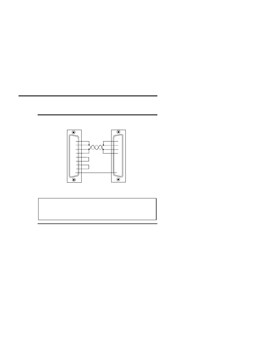
Figure 6 describes a 2 wire cabling scheme between a port on the
Titan/cPCI adapter to a port on the RS-485/422 peripheral.
Figure 6: RS-485/422 wiring diagram (2 wire)
RTS +
RTS -
CTS +
CTS -
TxD +
TxD -
RxD +
RxD -
RxD +
TxD +
RxD -
TxD -
RTS -
CTS -
RTS +
CTS +
SR
SR
Titan/cPCI adapter
RS-485 peripheral
3
1
4
2
5
6
9
7
8
Technical Tip
The RS-485/422 electrical interface consists of a differential
signaling scheme. You should always connect the signals
with twisted pairs