Connect Tech JB2 User Manual
Page 32
4-12
Chapter 4: Appendices – RS-485/422 Interface
Titan/cPCI User’s Manual, ver. 0.00
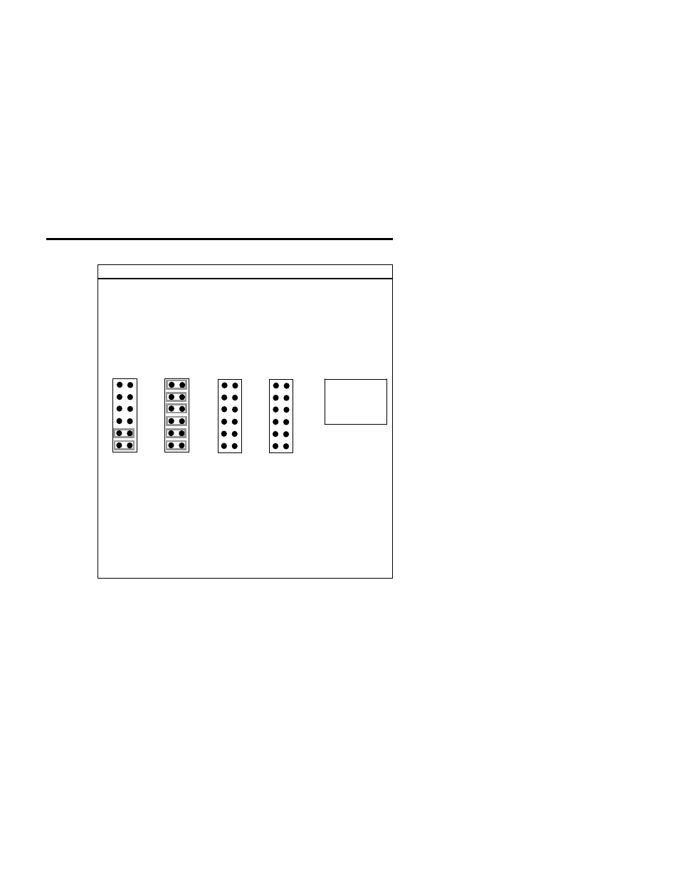
Example
The following example shows the settings on JC, JD, JE and JF
where RS-485 port 1 is terminated on RTS ± and TxD ±, the
RS-485 port 2 is set for bias/termination on RTS ±, TxD ±, CTS
±, and RxD ±, the RS-485 port 3 is not terminated, and port 4
is set for RS-232 on jumper block JB and therefore should not
be terminated
JC
PORT 1
Jumper Legend
1 = CTS terminator & bias
2 = CTS terminator & bias
3 = RxD terminator & bias
4 = RxD terminator & bias
5 = TxD terminator
6 = RTS terminator
JC1
JC2
JC3
JC4
JC5
JC6
JD
PORT 2
JD1
JD2
JD3
JD4
JD5
JD6
JE
PORT 3
JE1
JE2
JE3
JE4
JE5
JE6
JF
PORT 4
JF1
JF2
JF3
JF4
JF5
JF6
Technical Notes:
1. For full duplex and multi-drop slave you can jumper
positions 1, 2, 3, 4, 5, and 6, on the appropriate jumper
block (JC, JD, JE or JF) if you want them terminated.
2. For RS-232 ports do not jumper positions 1, 2, 3, 4, 5, and
6, on the appropriate jumper block (JC, JD, JE or JF).