Pin assignment (dvi), Dvi modes, Pin assignment 9 – Atlantis Land A05-19BM-F02 User Manual
Page 22: Technical information
Attention! The text in this document has been recognized automatically. To view the original document, you can use the "Original mode".
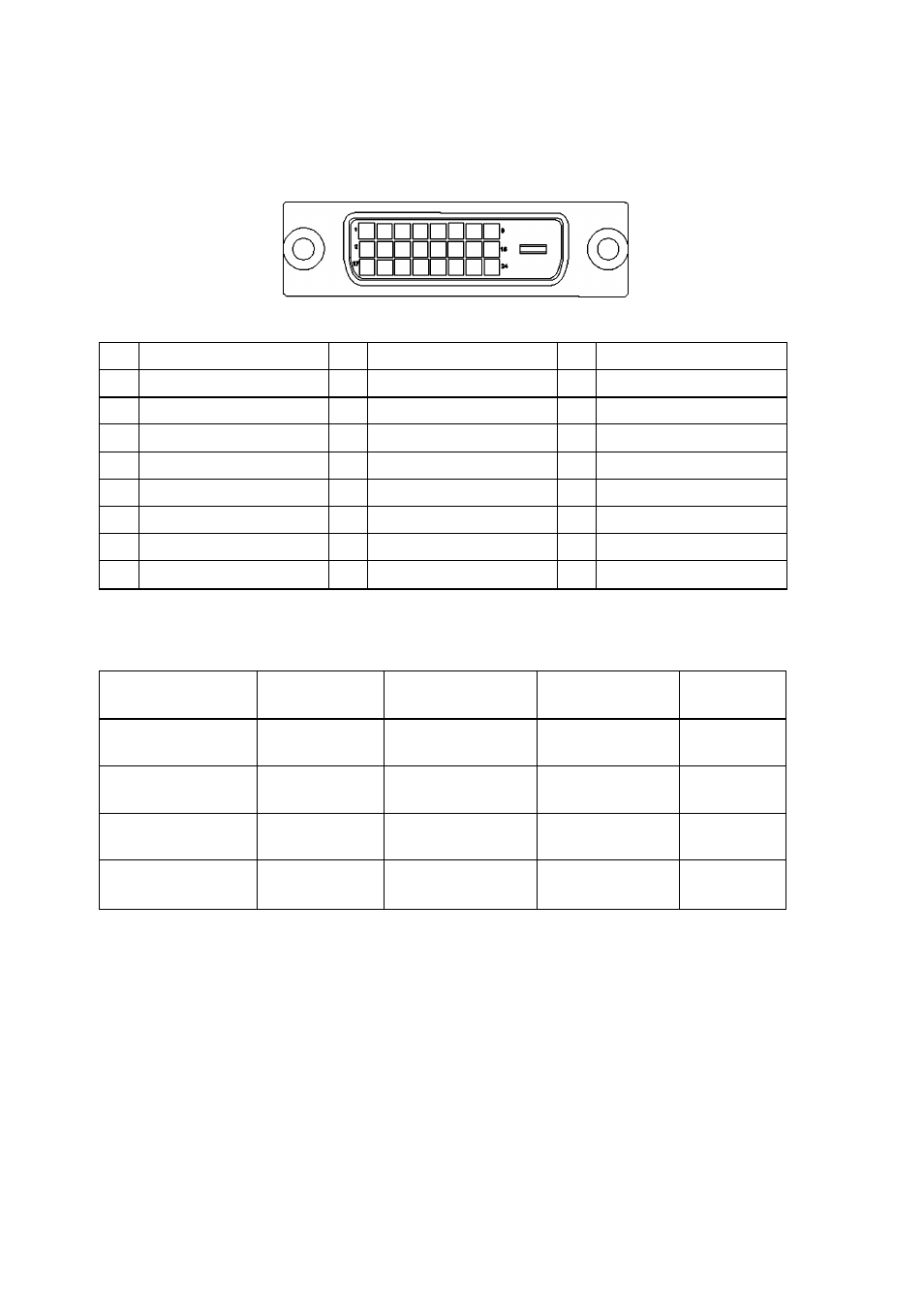
Pin Assignment (DVI)
TECHNICAL INFORMATION
DVI Connector
Pin
Signal Assignment
Pin
Signal Assignment
Pin
Signal Assignment
1
T.M.D.S. Data 2-
9
T.M.D.S. Data 1-
17
T.M.D.S. Data 0-
2
T.M.D.S. Data 2 +
10
T.M.D.S. Data 1 +
18
T.M.D.S. Data0+
3
T.M.D.S. Data 2/4 Shield
11
T.M.D.S. Data 1/3 Shield
19
T.M.D.S. Data 0/5 Shield
4
T.M.D.S. NC
12
T.M.D.S. NC
20
T.M.D.S. NC
5
T.M.D.S. NC
13
T.M.D.S. NC
21
T.M.D.S. NC
6
DDC Clock
14
+ 5V Power
22
T.M.D.S. Clock Shield
7
DDC Data
15
Ground (for +5V)
23
T.M.D.S. Clock +
8
No Connect
16
Hot Plug Detect
24
T.M.D.S. Clock-
DVI Modes
Resolution
VCLK(MHz)
Horizontal
Frequency(KHz)
Vertical
Frequency(Hz)
Standard
640*480
25.175
31.469
59.940
IBM VGA
800*600
40.000
37.879
60.000
VESA
1024*768
65.000
48.363
60.000
VESA
1280*1024
108.000
63.981
60.000
VESA
20
♦ ♦ ♦