Attaching the brake cable, Securing the cables (hardware e), Ahaching the starter rope (hardware c) – Bolens 111-518R000 User Manual
Page 6: Ahaching the rear wheels (hardware g)
Attention! The text in this document has been recognized automatically. To view the original document, you can use the "Original mode".
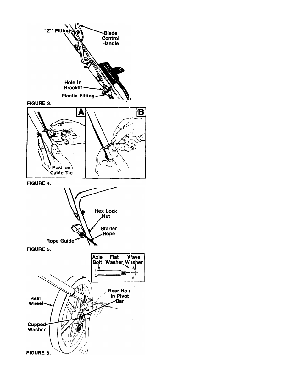
ATTACHING THE BRAKE CABLE
1. The brake cable is attached to the engine, and has
a “Z” fitting on the loose end. Route the brake
cable below the lower handle. Place end of cable
through the hole in the bracket as shown in figure
■3. Be careful not to bend or kink the cable at any
time. Push the plastic fitting until it locks into the
hole in the bracket.
A
WARNING: Brake cable must be assem
bled as shown for proper blade brake
operation.
2. Hook the “Z” end of the brake cable into the hole
in the blade control handle from the inside to the
outside as shown in figure 3.
SECURING THE CABLES (Hardware E)
Secure all cables to the left side of the handle as
follows.
A
WARNING: When attaching the control
cables, the cables must be routed to avoid
contact with all sharp edges and hot sur
faces to prevent damage to the cables,
which will render the controls inoperative.
1.
Insert posts on cable ties into holes provided on
the lower handle. The holes may be either on the
-------inside or outside of the handles. See figure 4A.
2. Secure the cables with the cable ties. See figure
4B.
3. Trim excess ends of cable ties.
AHACHING THE STARTER ROPE (Hardware C)
1. The starter rope is inside the top of the engine. Ad
ditional rope may be wound around the starter han
dle. If so, unwind the rope from the handle.
2. With the spark plug wire disconnected and
grounded, depress the blade control handle and
pull the rope out of the engine.
—3. Place the rope guide around the starter rope, so
the rope guide is positioned as shown (bends
downward slightly). Insert the rope guide through
the right side of the lower handle, and secure with
hex lock nut. See figure 5.
AHACHING THE REAR WHEELS (Hardware G)
-Assemble the rear wheels as follows. See figure 6.
1. Move the wheel height adjusters so the deck is in
the lowest cutting position.
2. Lift the rear of the unit up and biock securely.
3. Place one large flat washer on axle bolt, then the
wave washer (cupped side against the flat washer
as shown in figure 6, inset).
4. Insert axle bolt through one rear wheel. Place
cupped washer on axle bolt (crowned side of
washer goes against the wheel).