Bolens 114-530 A User Manual
Page 4
Attention! The text in this document has been recognized automatically. To view the original document, you can use the "Original mode".
CAUTION
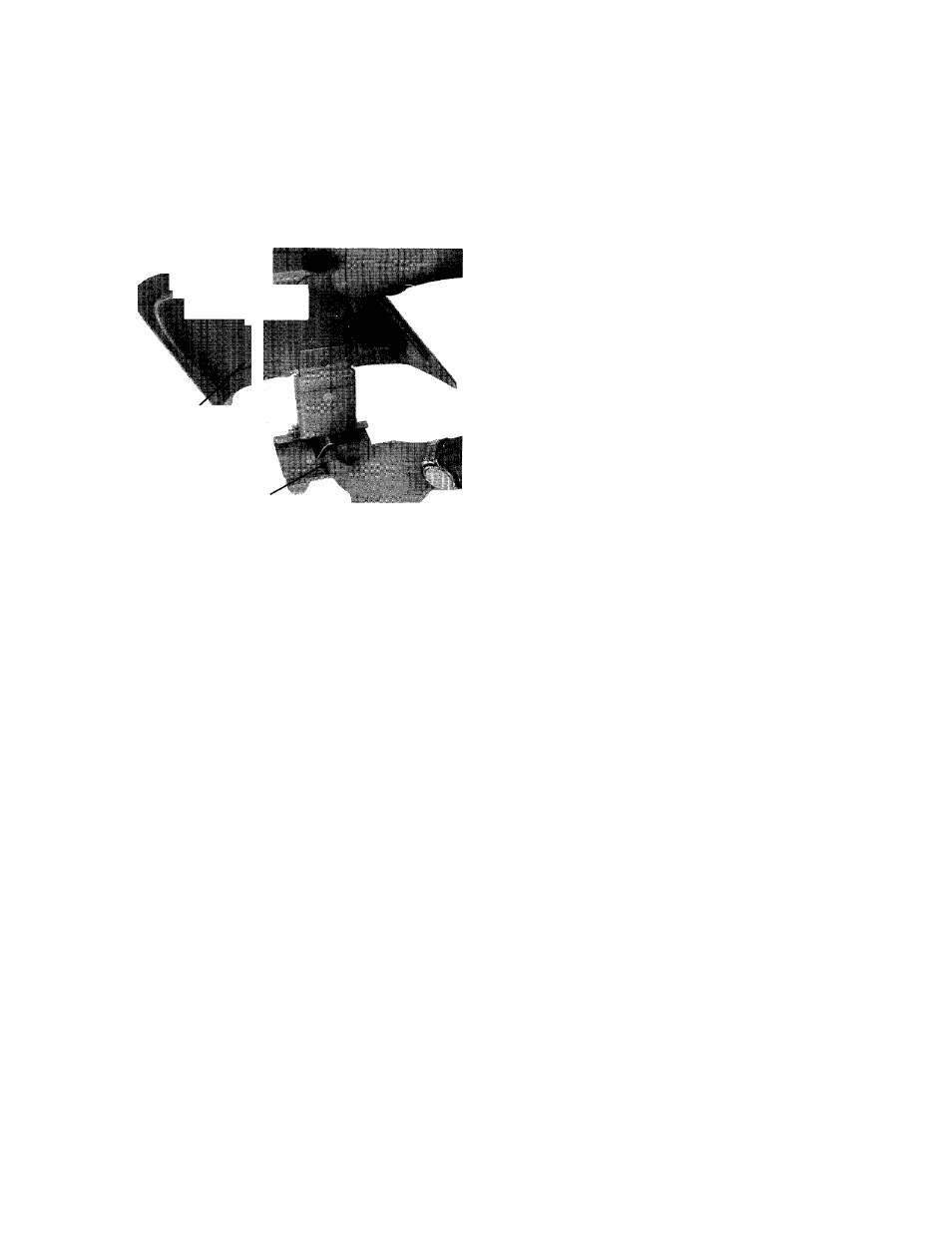
Please note that the chute deflector on
your mower is in an upright position.
It is held in that position by a shipping
block. This block is used for shipping
purposes only. It must be removed and
discarded before your mower is put
into operation.
Chute Doficctoi
Shipping Block to be Removed
NOTE
For shipping purposes your mower is
set with the wheels in a low cutting
height position. For best results raise
the cutting position until it is deter
mined which height is best for your
lawn. See adjustments.
OPERATION
8. Put blade into motion by moving blade control
handle to "ON" position.
To engage the blade with the engine running . . .
a. Move the throttle control lever to "FAST" posi
tion.
b. Engage the blade engagement handle SLOWLY.
c. Adjust engine speed.
9.
A brief break-in period is essential to insure maxi
mum engine and mower life. This consists of run
ning the engine at half speed for a period of time
required to use one tank of gasoline. It is also rec
ommended to change crankcase oil after the first
five hours of operation or as operating conditions
dictate. Always check oil before operating the
mower. BE SURE CRANKCASE IS FULL.
10. Proper lubrication must be maintained at ali times.
11. Appropriate clothing should be worn when cut
ting brush or heavy weeds. Safety shoes and safe
ty glasses are highly recommended.
12. The engine is stopped by moving the throttle con
trol lever to "STOP" position.
ADJUSTMENT
Handles may be adjusted by changing the position
of the lower support mounting holes. When this
change is made, it may also be necessary to check
the adjustment of control rod. See Step 9 in AS
SEMBLY INSTRUCTIONS
1. Before starting engine, check LUBRICATION IN
STRUCTIONS.
2. Check lockout control handles for proper opera
tion. If too great a pressuré is needed to operate
these controls, damage can be done to both the
mechanism and the rods. Readjust so only slight
pressure is needed to operate both the blade en
gaging control and the self-propelled lockout con
trol. See ASSEMBLY INSTRUCTIONS Step 9.
3. Service engine with gasoline and oil. See engine
instructions for complete care and maintenance of
engine. READ DIRECTIONS CAREFULLY.
4
.
Be sure engine crankcase is filled to capacity with
proper grade of oil.
5. Move both control handles to "OFF" position.
6. Move throttle control lever to "CHOKE" position.
7.
Crank engine. Move throttle control lever to
"FAST" position as soon as engine fires. Use choke
as needed to keep engine running during warm
up period.
2. Control rod adjustments are made as shown in AS
SEMBLY INSTRUCTIONS Steps 9 and 12.
3.
Cutting height adjustment is made by removing
and moving axle bolts to the desired positions. All
axle bolts must be mounted in the same relative
position to the deck. When wheels are mounted to
the deck, the crown shape washers must be assem
bled with the crown away from the deck. This is
necessary to prevent the axle bolts from loosening.
4. If throttle adjustment becomes necessary, the throt
tle control wire may be reset as follows:
a.
Loosen, but do not remove, screw securing
throttle control wire assembly at engine.
b.
Move throttle control lever on handle to
"CHOKE" position.
c. Move lever to which control wire is fastened to
engine to full choke position. Retighten screw
to secure throttle control wire assembly.