Attaching the hoses, Final assembly, Operation – Bolens 522 User Manual
Page 8: Initial preparation, Service engine with gasoline and oil as
Attention! The text in this document has been recognized automatically. To view the original document, you can use the "Original mode".
Reservoir
Tank
/ /
Suction
Hose
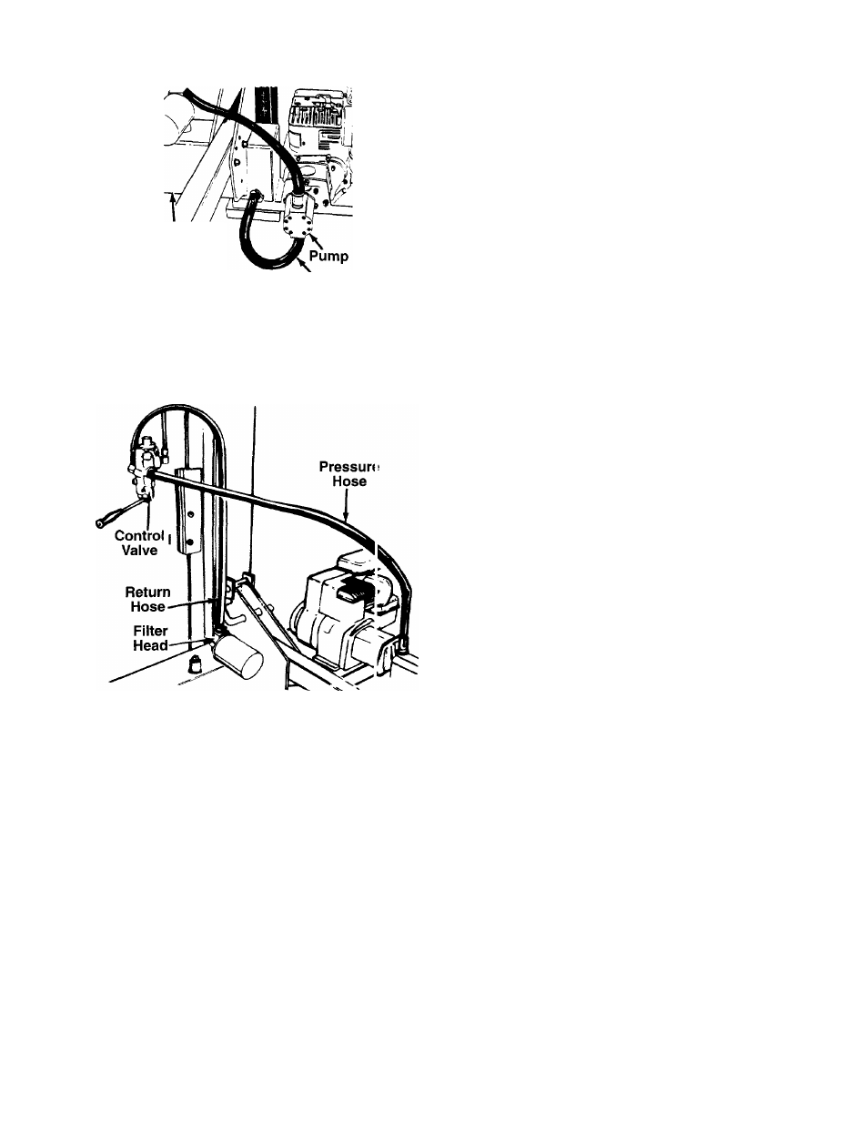
FIGURE 9.
FIGURE 10.
ATTACHING THE HOSES
Suction Hose
1. The suction hose is attached to the reservoir tank,
beneath the engine mounting bracket. See figure
9. Loosen the hose clamp on the free end of the
hose using a screwdriver.
2. Remove the protective cap from the fitting on the
bottom of the pump (some oil may flow from
pump). Attach the end of the suction hose to the
fitting on the bottom of the pump. Place the hose
clamp at the base of the fitting, and tighten
securely.
NOTE: Check all hose ends and remove any plugs.
Discard plugs.
Return Hose
1. The return hose is attached to the top of the con
trol valve. Loosen the hose clamp on the free end
of the hose using a screwdriver. Cut off the secur
ing strap.
2. Remove the protective cap from the fitting on top
of the filter head. Attach the end of the hose to the
fitting on top of the filter head. See figure 10.
Place the hose clamp at the base of the fitting,
and tighten securely.
Pressure Hose
The pressure hose is attached to the top of the valve.
Route the hose as shown in figure 10. Secure the
pressure hose to the bottom of the pump, using two
wrenches.
FINAL ASSEMBLY
1. Pull the locking rod on the beam support/latch
bracket away from the log splitter tongue (refer to
figure 5), and pivot it down. Carefully lower the
wedge, beam and cylinder assembly to the
horizontal position. Secure the beam with the
locking rod.
2. Make certain all nuts, bolts and hose clamps are
tightened securely.
3. Before operating the log splitter, make certain
to follow “Initial Preparation” instructions in
Operation section.
OPERATION
INITIAL PREPARATION
1. Place the log splitter on a dry, firm, leve surface.
Block the wheels.
2. Service engine with gasoline and oil as
instructed in the separate engine manu< I packed
with your log splitter.
3. Lubricate the beam area where splitting wedge
will slide with engine oil (DO NOT USE GREASE).
Make certain to oil both front and back of the
beam face.
4. Fill the reservoir tank as follows.
a. Remove reservoir vent plug. See fgure 11.
Using Dexron II automatic transmission fluid,
or
low
non-foaming hydraulic fluid, fill reser
voir to the top. Replace vent plug seci rely.
NOTE: Total capacity of system is approximately 4
gallons.
b. Disconnect the spark plug wire. Prime the
pump by pulling the recoil starter, to turn
the engine over, approximately 10 times.
Reconnect the spark plug wire.
c. Start engine. Use the control handle to extend
the wedge to the far extended position. Leave
the wedge in this position (do not retract).
d. Refill tank to within 1-1/2" to 2" from the top of
the tank.
e. Now retract the wedge. Extend and retract the
wedge fully 10 to 12 complete cycles to
remove trapped air in the system (system is
“self-bleeding”).