Installing the hitch, Attaching the wedge, beam and cylinder assembly, Warning: use extreme caution as – Bolens 522 User Manual
Page 7: Ahaching the engine and pump assembly, Ahaching the control handle
Attention! The text in this document has been recognized automatically. To view the original document, you can use the "Original mode".
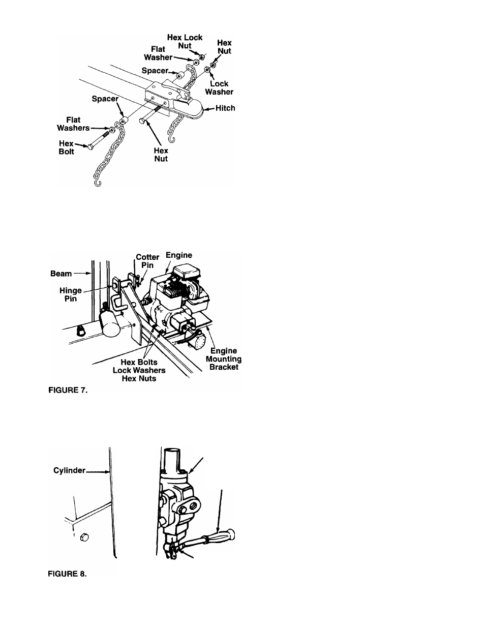
FIGURE 6.
Control
Valve
Control
Handle
INSTALLING THE HITCH
1. Using two 9/16" wrenches, remove the hardware
which is assembled through the sides of the hitch.
Do not remove the flat washer, chain and spacer
from under the head of one hex bolt.
2. Place the hitch in position on the end of the
tongue as shown in figure 6. Using hole closest to
the jack stand, insert the hex bolt (with hardware
attached) through hitch and tongue. Pivot the first
chain link on the hex bolt so it faces the ball end of
hitch.
3. Place the other spacer, safety chain and flat
washer on the hex bolt, with the first link of the
chain also facing the ball end of hitch. Secure with
hex lock nut.
4. Secure front of tow hitch to tongue with the other
hex bolt, lock washer and hex nut just removed,
using the forward hole in hitch and tongue.
5. Tighten both bolts and nuts securely using two
9/16" wrenches.
ATTACHING THE WEDGE, BEAM AND CYLINDER
ASSEMBLY
1. For shipping purposes, the pressure hose is
attached to the pump on the engine, and to the
control valve on the cylinder (see figure 8). Dis
connect the pressure hose from the pump.
2. Stand the wedge, beam and cylinder assembly
upright, with cylinder to the top.
WARNING: Use extreme caution as
assembly is very heavy.
A
Clevis Pin
Cotter Pin
3. Remove the cotter pin and the hinge pin, located
beneath the beam assembly. Move the reservoir
tank assembly in position against the beam. See
figure 7. Line up holes by lifting hitch end of
assembly.
4. Insert hinge pin just removed through welded
brackets on beam and reservoir tank assembly.
Secure with cotter pin, bending the ends of the pin
in opposite directions.
AHACHING THE ENGINE AND PUMP ASSEMBLY
Place the engine and pump assembly in position on
the engine mounting bracket as shown in figure 7.
Secure with hardware found in the plastic bag. Insert
hex bolts from the top. Secure with lock washers and
hex nuts, tightening securely.
AHACHING THE CONTROL HANDLE
1. The control handle may be taped to the stripper
half for shipping purposes only. If so, remove the
tape, and attach the handle as instructed in next
step.
2. The bottom of the control handle is already
attached to the control valve. Remove the cotter
pin and clevis pin which are attached to the valve.
Place handle in position, and secure to the valve
using the cotter pin and clevis pin. See figure 8.