Bolens 111-064A User Manual
Page 7
Attention! The text in this document has been recognized automatically. To view the original document, you can use the "Original mode".
Upper Handle
----- Halves
.■-V
•iff
Hex Bolts (B)
Hex Bolts (B)
FIGURE 5.
Hex Lock
Nut (D)
8.
Assemble the upper handle halves to lower
handle using five hex bolts (B) and lock nuts
—(D). Only tighten finger tight. See figure 5.
(Throttle Control Optional)
9.---- Piace the tab on throttle control between the
upper handle halves at top holes. Secure with
hex bolt (C) and hex lock nut (D) provided in
-------hardware pack. See figure 6.
10. Tighten securely all six hex bolts and hex lock
nuts with 7/16" wrench.
FIGURE 6.
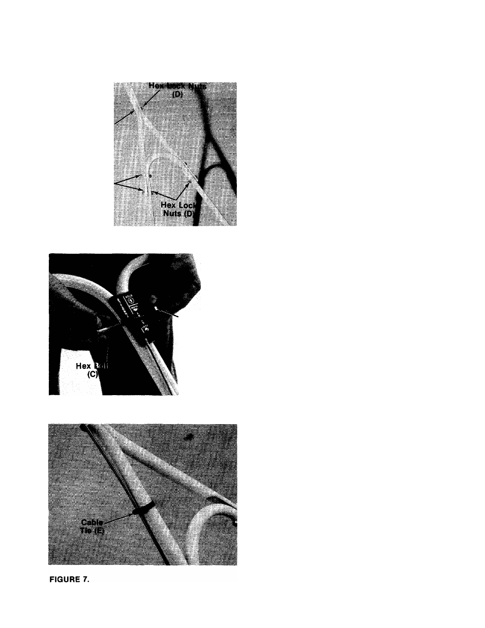
11.
Secure throttle control wire to handle with
two cable ties (E) provided in hardware pack.
------ See figure 7.
12. Check all nuts and bolts for correct tightness.
13. Slip hand grips (A) on the upper end of each
handle. They will slip on more easily if you
first soak them in warm, soapy water.