Adjustments – Bolens 111-064A User Manual
Page 10
Attention! The text in this document has been recognized automatically. To view the original document, you can use the "Original mode".
4. Be sure that lawn is clear of stones, sticks,
wire, or other objects which could damage
lawn mower or engine. For best results and to
insure more even grass distribution, do not
mow when lawn is excessively wet.
IMPORTANT
After striking a foreign object, stop
the engine. Remove wire from spark
plug, thoroughly inspect the mower
for
any
damage, and repair the
damage
before
restarting
and
operating the mower.
High Position
ADJUSTMENTS
A
CAUTION
Do not at any time make any adjust
ment to lawn mower without first
stopping
engine
and
disconnecting
spark plug wire.
EASY CUTTING HEIGHT
An adjusting plate and thumb lever at each wheel
position provides cutting height adjustment. Each
adjusting plate has five holes. Height of cut will
be changed when the thumb lever is moved from
one hole to another. Simply depress thumb lever
towards
wheel
and
move
wheel
and
lever
assembly to desired position. All wheels must be
placed in the same relative position.
CUTTING HEIGHT
Adjustment may be made by removing and moving
wheel studs to desired position. Cutting heights
will be raised as wheel studs are moved to a lower
hole and lowered as wheel studs are moved to a
higher hole in the deck. AM wheel studs must be
mounted in a relative position to the deck. See
figure 4.
HANDLE POSITION
The upper handle can be adjusted to a high or low
position. The adjustment is made by removing the
hex lock nuts or hand knobs and curved carriage
bolts and reassembling in the other position. See
figure 13.
FIGURE 13.
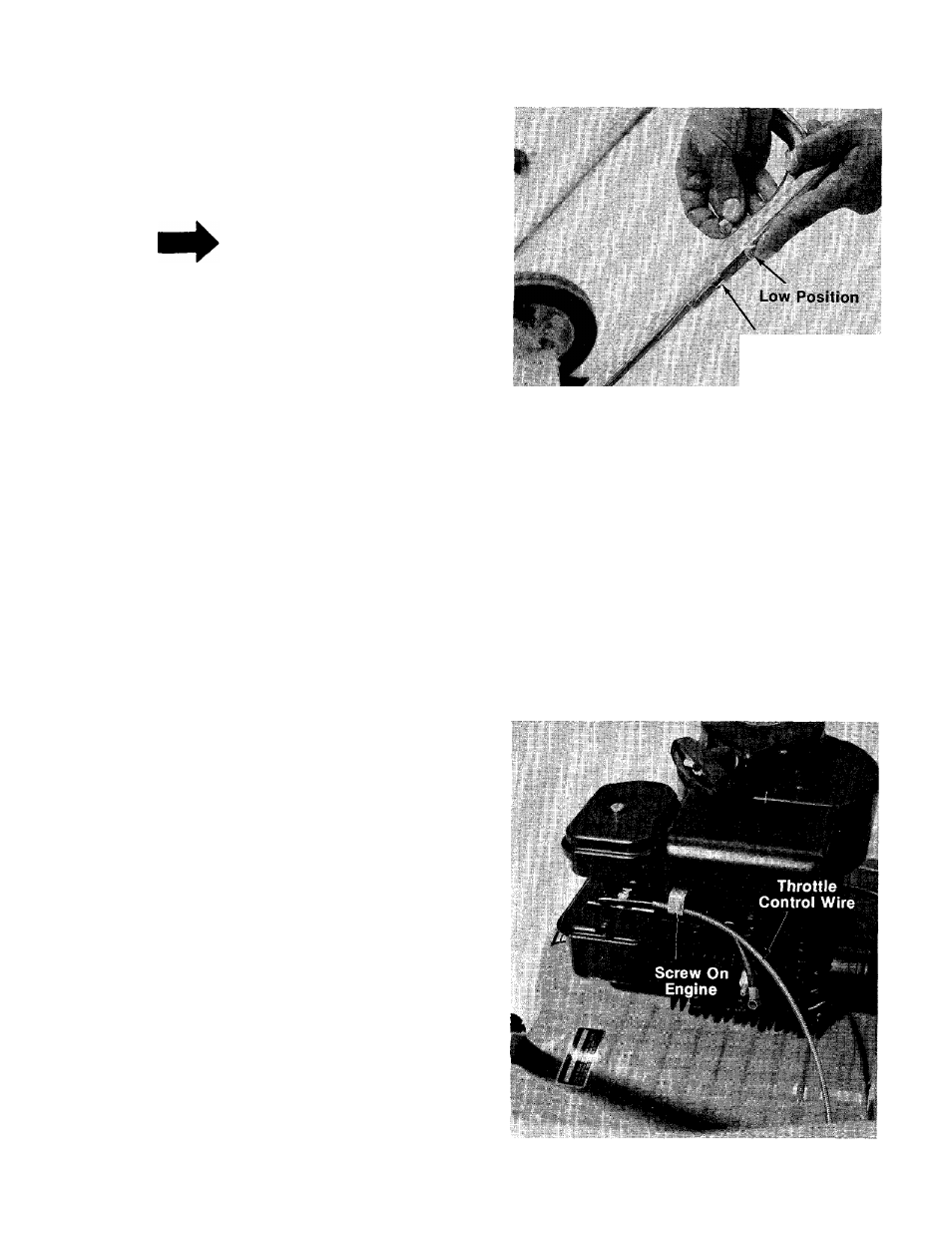
THROTTLE
If
adjustment
becomes
necessary,
the
throttle
control wire assembly can be reset as follows;
1.
Loosen, but do not remove, screw securing
throttle control wire assembly at engine. See
figure 14.
2.
Move throttle control lever on handle to
“FAST” position.
3. Move lever, to which control wire is fastened
at engine, to full open position and retighten
screw
to
secure
throttle
control
wire
assembly.
FIGURE 14.
10