Figure 5 - locating the unit, Materials, Table ii – Bryant SERIES D 453 User Manual
Page 5: Insulation, Height of coil above unit, Water coil connections
Attention! The text in this document has been recognized automatically. To view the original document, you can use the "Original mode".
□
Avoid
Open
Windows
Sleeping
Qu Öfters
Avoid
“Ells"
Gorage
Living
Area
Air
Flow
□ %
Good
Location
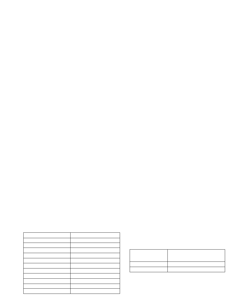
Figure 5 - Locating the Unit
15"--
Minimum
A70022
Materials
1. Chilled Water Piping
a. Use Bryant Quick-Connect Tubing.
b. Polyethylene pipe—satisfactory substitute; use
medium density flexible pipe whose wall thick
ness approximates Schedule 40 pipe (Commercial
Standard CS 255-63). Pipe must be made from
virgin material. Do not use pipe manufactured
from reclaimed material.
c. Copper—satisfactory substitute.
d. Galvanized—satisfactory substitute.
2. Fittings
a. Galvanized—use when possible.
b. Brass —satisfactory substitute.
Pipe Length and Diameter
Table I shows the maximum length of pipe of different
diameters that can be used between the pump dis
charge and the coil inlet and still maintain minimum
allowable (design) water flow rate.
1. Multiply table values by two to obtain the total
length of pipe from chiller to coil and return.
2. Length is measured along the pipe path and there
fore includes vertical distance between the water coil
and the chiller.
3. Lengths shown in Table I are based on using a total
of eight elbows in the entire water line (chiller to coil
and return). Lengths are predicated on the use of a
Bryant matching water coil. For greater distances use
larger size pipe.
TABLE II
Water Flow Rate at Various External Pressures
Water Flow Rate - GPM
Pressure External to Unit
5
38.3
6
37.5
7
36.7
8
35.8
9
34.7
10
33.5
11
32.5
12
31.0
13
29.5
14
27.5
15
26.0
4. For calculating chilled water pipe size for coils
not listed, use friction loss method with allowance for
coil pressure loss. Refer to coil instructions for pressure
loss at design water flow rate. Refer to Table II show
ing available head with standard pump drive.
Insulation
1. Insulate both supply and return lines.
NOTE: Bryant Quick-Connect Tubing is preinsulated.
2. Material should be of good quality and be covered
with a good vapor barrier. Armaflex or equivalent is
recommended. Use 1/2 inch wall thickness. (Bryant
Quick-Connect Tubing is preinsulated.)
Height of Coil Above Unit
The maximum vertical distance from Model 48-453
Chiller to top of coil is 30 feet.
Water Coil Connections
1. If the cooling coil is used in connection with a
heating unit and the heating unit is not approved for
installation downstream from the cooling coil, install
the cooling coil in parallel with or downstream from
the heating unit. This will avoid condensation in the
heating unit. If the coil and heating unit are installed
in parallel, the dampers or other means used to control
flow of air should be adequate to prevent chilled air
from entering the heating unit; if manually operated,
the dampers shall be equipped with some means to
prevent operation of either unit unless the dampers are
in full heat or full cool position.
2. If the coil is located in a warm air stream, do not
connect polyethylene pipe directly to the coil. Connect
a minimum of 24 inches of copper or galvanized pipe
to both the coil inlet and outlet; then connect the
polyethylene pipe to these nipples.
NOTE: not required when using Bryant Quick-
Connect Tubing.
3. On installations where the water in the outside piping
freezes and the coil is in a heated air stream, precautions
must be taken to provide for water expansion. The
connecting polyethylen'e pipe acts as an expansion
vessel if there is sufScient footage in the heated space
(space not subject to freezing). Table III shows the
minimum lengths (total inlet and outlet) of polyethylene
piping of various diameters that are required to provide
adequate expansion volume.
TABLE III
Nominal
Pipe Size
Inches
Length of Polyethylene
Pipe in feet
3/4
32
1
20
If the total polyethylene chilled water line footage in
the heated space is not as long as the minimum values
shown in the table, tee a vertical pipe of sufficient
volume into either of the coil connections to provide
-
5
-