Using the mulcher, Cuning height adjustment, Handle height adjustment – Bolens 123E898E190 User Manual
Page 8: Figure 12, Drive clutch control adjustment, Adjustments
Attention! The text in this document has been recognized automatically. To view the original document, you can use the "Original mode".
A
WARNING: If you strike a foreign object,
stop the engine. Remove wire from spark
plug, thoroughly inspect the mower for
any damage, and repair the damage
before
restarting
and
operating
the
mower. Extensive vibration of the mower
during operation Is an indication of dam
age.
The
unit
should
be
promptly
inspected and repaired.
USING THE MULCHER
For effective mulching, do not cut wet grass because
it tends to stick to the underside of the deck, prevent
ing proper mulching of grass clippings. New or thick
grass may require a narrower cut. The ground speed
should be adjusted to the condition of the lawn. If
mowing has been delayed and the grass has been
allowed to grow in excess of 4", mulching is not rec
ommended. Mow using the grass bag to reduce the
grass
height
to
3-1/4"
maximum
before
mulching.
Never cut more than one-third off the total length of
the grass at any one cutting.
ADJUSTMENTS
A
WARNING: Do not at any time make any
adjustment to lawn mower without first
stopping engine and disconnecting spark
piug wire.
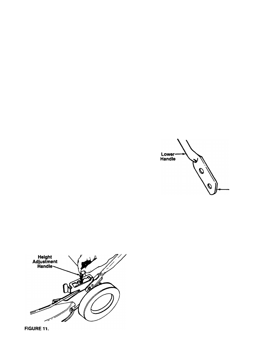
CUniNG HEIGHT ADJUSTMENT
The height adjustment handles for the wheels are
located on the left side of the deck. The handles may
be placed in one of nine cutting height positions. See
figure 11.
For rough or uneven lawns, move the height adjust
ment handle to a position which will give a higher cut
ting height. Both front and rear handles must be
placed in the same relative position.
HANDLE HEIGHT ADJUSTMENT
Your mower is shipped with the handle ready to
assemble in the higher height position. To lower the
handle height, proceed as follows.
1.
Remove the upper handle by removing the hand
knobs and carriage bolts. Lay the upper handle
out of the way, being careful not to bend or kink
the cables.
2.
Remove the hairpin clips from the weld pins on
the handle brackets. Press outward on the legs of
the lower handle, and remove it from the mower.
3.
Turn the lower handle around so the flat on the
bottom is facing upward as shown in figure 12.
Reassemble, placing the bottom holes in the han
dle over the weld pins in the handle mounting
bracket.
4. Reassemble the upper handle.
5.
Place the hairpin clips in the inner holes in the
weld pins.
Flat
FIGURE 12.
DRIVE CLUTCH CONTROL ADJUSTMENT
Use the adjustment wheel located on the underside of
the clutch control housing to tighten the drive belt if
mower does not self-propel with the drive clutch control
engaged, or if drive belt is slipping {unit hesitates while
engine maintains the same speed). See figure 13.
In addition, the adjustment wheel may also be used to
determine the position in which the drive clutch con
trol is engaged. If it is more comfortable to have the
drive engaged with the lever further away from the
handle, tighten the drive belt.
Make certain to retest the unit for neutral as instructed
in the Operation Section. Move the adjustment wheel
in the opposite direction to loosen the drive belt if nec
essary.