Replacing the rear discharge chute, Blade control handle, Throhle control – Bolens 123E898E190 User Manual
Page 5: Ignition switch, Drive clutch control, Shift lever, Controls
Attention! The text in this document has been recognized automatically. To view the original document, you can use the "Original mode".
Ribs
Rear
Panel
Rear
Discharge
Chute
Assembly
^ Shoulder
Bolt
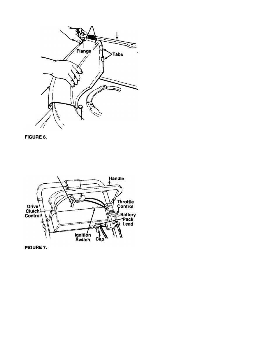
REPLACING THE REAR DISCHARGE CHUTE
To replace the rear discharge chute assembly, pro
ceed as follows.
Slide the ribs on the discharge chute assembly under
the flange on rear panel as you insert the side of the
-discharge chute under the two tabs. See figure 6.
The
edge
of
the
discharge
chute
assembly
goes
under the shoulder bolt on deck. Push down on the
chute assembly, and slide the bottom corner slots
over the bolts on side of deck.
Press down on the discharge chute assembly and
secure with wing nuts. Make certain wing nuts are
seated properly.
A
WARNING: Never operate your unit with
out either the side chute deflector,
mulching plug or entire rear discharge
chute and grass catcher assembly in
place.
CONTROLS
Shift Lever
Blade
Control
BLADE CONTROL HANDLE
A
WARNING: This control mechanism is a
safety device. Never attempt to bypass
Its operations.
The blade control handle is located on the upper han
dle of the mower. See figure 7. The blade control han
dle must be depressed in order to operate the unit.
Release the blade control handle to stop the engine
and blade.
A
WARNING: The blade will be rotating
whenever the engine is running.
THROHLE CONTROL
The throttle control is located on the left side of the
upper handle. It is used to regulate the engine speed.
A
WARNING: The throttle control cannot be
used to stop the engine.
IGNITION SWITCH
The ignition switch is located on the left side of the
handle panel. It is used for starting only. See figure 7.
DRIVE CLUTCH CONTROL
Squeezing the drive clutch control engages the drive
mechanism to the rear wheels. Releasing the clutch
control stops the rear wheels from driving. Release
the drive clutch control to slow down when negotiating
an obstacle, making a turn or stopping. See figure 7.
SHIFT LEVER
The six speed shift lever is located on the drive clutch
control housing on the upper handle. See figure 7.
This lever is used to select the operating speed of the
mower. Release the drive clutch control when chang
ing speeds.
IMPORTANT: Move the shift lever ONLY when the
engine is running. Shifting the speeds with the
engine off can cause damage to the unit.