Tools required for assembly, Removing unit from carton, Ahaching the tailpiece and depth stake – Bolens 390 User Manual
Page 4: Ahaching the handle assembly, Ahaching the clutch control cable(s), Assembly instructions
Attention! The text in this document has been recognized automatically. To view the original document, you can use the "Original mode".
ASSEMBLY INSTRUCTIONS
IMPORTANT: This unit is shipped WITHOUT GASO
LINE or OIL. After assembly, see separate engine
manual for proper fuel and engine oil recommen
dations.
NOTE:
Left and right is determined from the
i
operator's
position, standing behind the tiller.
TOOLS REQUIRED FOR ASSEMBLY
(1)-1/2" Wrench or Socket*
(l)-Pair of Pliers
(1)-3/8" Wrench*
*An adjustable wrench may be used.
This owner's guide covers two différer t model
tillers. Model 340 has forward tine drive only.
Model 390 has both forward and reverse ti ie drive.
Follow only the instructions which pertain to your
model tiller. See the model plate on your tiller for
the correct model number.
REMOVING UNIT FROM CARTON
1. Remove staples, break glue on top flaps, or cut
tape at carton end and peel along top fla ) to open
carton.
2. Remove all loose parts included with unil.
3. Cut along dotted lines and lay carton dovm flat.
4. Remove packing material.
5. Roll or slide unit out of carton. Check carton
thoroughly for loose parts.
6. Extend control cable(s) to the rear of the tiller and
lay them on the floor. Be careful not to bend or
kink control cable(s).
All hardware required for assembly has been placed in
position on the tiller.
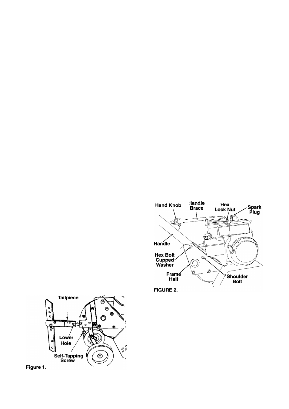
AHACHING THE TAILPIECE AND DEPTH STAKE
Remove the two self-tapping screws which a'e on the
front of the tailpiece. Slide the tailpiece into the frame,
with the lower hole in the tailpiece toward he front.
Secure with screws just removed. (See Figur: 1)
AHACHING THE HANDLE ASSEMBLY
1. Remove the hex bolt and cupped washer from the
top right side of the frame halves. Hold the cable
guide bracket on the left side of the frame as it will
fall when the bolt is removed. (See Figure 2)
2. Insert the handle assembly between the two
frame halves. Insert the hex bolt just removed
through the frame halves, handle assembly, and
into the cable guide bracket (notch in cable guide
bracket goes over the flange on the frame).
Tighten securely.
3. Tighten the shoulder bolt on the frame, just below
the end of the handle.
4. Loosen the hand knob which secures the handle
brace to the handle assembly.
5. Remove the hex lock nut from on top of the
engine, just behind the spark plug. Attach the
curved end of the handle brace to the top of the
engine, using hex lock nut just removed. Tighten
securely. (See Figure 2)
6. Select one of the three handle height positions
(three notches in welded bracket), and tighten the
hand knob to secure the handle in desired posi
tion. Make certain carriage bolt is seated
securely into one of the three positions provided.
AHACHING THE CLUTCH CONTROL CABLE(S)
FORWARD CABLE
Attach the end of the forward cable to the bracket
underneath the handle assembly as follows. (On
model 390, the forward clutch cable is the cable which
Is attached closer to the rear of the tiller.)
1. Loosen the hex nut on the threaded rod near the
end of the cable, and move it up the rod as far as it
will go.
2. Unthread the rod from the rest of the cable. Hook
the “Z” end of the rod into the bracket underneath
the handle assembly from the right hand side.
(See Figure 3)