Note, Contents of hardware pack: (see figure 1), Lower handle installation – Bolens 82-0629 User Manual
Page 5: Upper handle installation, Assembly instructions
Attention! The text in this document has been recognized automatically. To view the original document, you can use the "Original mode".
V/»!777777^mгL‘2/>
ASSEMBLY INSTRUCTIONS
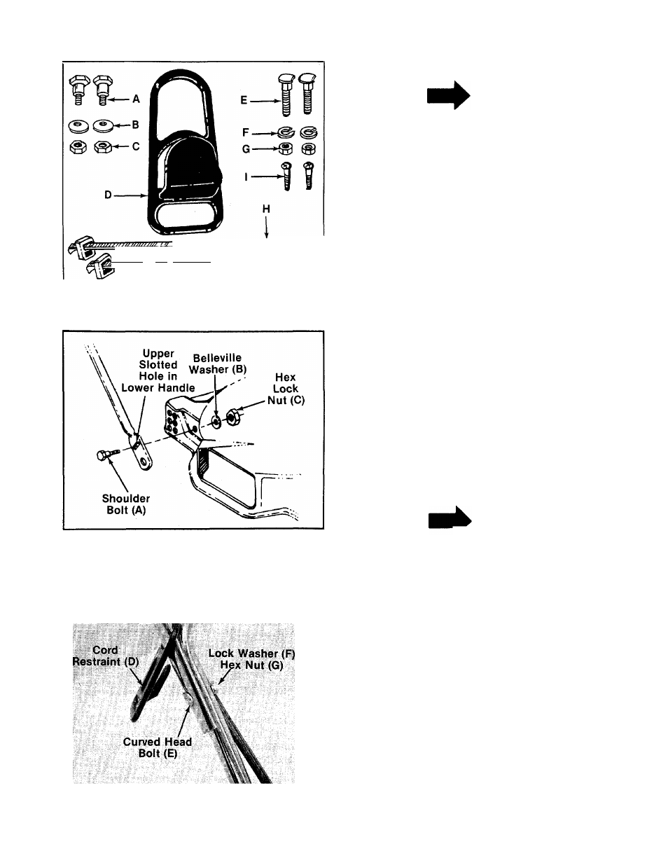
FIGURE 1.
NOTE
Reference to right or left hand side
of the mower is observed from the
operating position.
-CONTENTS OF HARDWARE PACK: (See figure 1)
A (2) Shoulder Bolts
B (2) Belleville Washers 5/16" I.D.
C (2) Hex Lock Nuts 5/16-18 Thread
D (1) Cord Restraint
E (2) Curved Carriage Bolts
F (2) Lock Washers 5/16" I.D.
G (2) Hex Nuts 5/16-18 Thread
H (2) Cable Ties
I (2) Self-Tapping Screws
J (1) Plastic Plug (Not Shown)
FIGURE 2.
1. Remove lawn mower and loose parts from car
ton. Make certain all parts and literature have
been removed from the carton before the car
ton is discarded.
2. Extend the control cord and place on the floor.
Be careful not to bend or kink control cord.
LOWER HANDLE INSTALLATION
Line up the upper slotted hole in lower handle
with the mounting hole on deck. Place shoulder
-bolt (A) through lower handle and deck. See figure
2. Place belleville washer (B) on the shoulder bolt,
with the cupped side of the washer against the
deck. Secure with hex lock nut (C).
NOTE
It may be necessary to bend the
ends of the lower handle inward
slightly to obtain a tight fit against
the deck.
UPPER HANDLE INSTALLATION
1.-Place the cord restraint (D) onto the upper
------handle. See figure 3.
2. Place the upper handle in position over the
lower handle. The two holes for the
motor/blade control must be on the right hand
side of the handle. Secure the upper handle
using the curved head bolts (E), lock washers
(F) and hex nuts (G) as shown in figure 3. Make
sure the cord restaint is on the right side of
the handle.
FIGURE 3.